To see if I'm on the air right now click here
Showing posts with label TZ-20 RF Amp. Show all posts

Wednesday, September 19, 2018

Winter 2018-19 Boat Anchor Season

As summer wraps up here and turns into fall I start shifting from QRP-In-The-Park to Boat-Anchors-In-The-Basement and the winter contest/operating event season. One station in the works here is a moderate capability mid 30s CW setup using a couple of TZ-20s (at about 50 watts) in the final and a National FBX-A receiver. It qualifies nicely for the AWA Linc Cundall Memorial CW Contest.

I've now finished up the transmitter power supply so I'll soon be testing it out on the air. The transformer is rated for 560V at 270mA so should certainly easily handle my 50-70W transmitter. At 31 pounds, mostly iron, I don't plan to move this one around much.

Next on the to-do list is to go through the FBX-A getting it on the air.

Friday, November 25, 2016

Thanksgiving Day Power Supply

After Thanksgiving Dinner this year I took the opportunity to make progress on the power supply for my 1939 transmitter.

I completed the  500 VDC and 7.5 VAC sections needed for the amplifier.  PSU Designer II indicated that I needed to allow for almost 2000 volts across each of the diodes in the bridge rectifier. I ended up using two 1000 PIV diodes in series for each leg of the bridge. This is a boat anchor power supply with silicon hidden under the chassis. It needed some glow. I added a type 80 rectifier connected only to 5 VAC so that it would look right. After all, real radios need to glow in the dark.


Eventually I'll add components to power the oscillator/buffer stage including 250 VDC, 150 VDC and 2.5 VAC. In the meantime I can drive the amplifier with either my Utah Jr or Meissner Signal Shifter.

Monday, January 20, 2014

AWA Linc Cundall Memorial OT CW Contest

Between 80 and 40 I managed twelve contacts using my National HRO Sr and TZ-20 transmitter with a low hung inverted L antenna. By contesting standards not a lot but still better than any of my LC QSO counts going back 20 years.

I worked nothing to the west but I did manage Qs to Canada, the east coast and southwest. I heard N2BE a lot. Too bad I could only work him once per band. I was surprised to not hear many of my MN friends on the air. Of the eight I worked in the BK I only heard three on for the LC.

I have grown to depend on the Reverse Beacon Network to help me decide if the band is dead. If I call CQ and I don't get a lot of feedback from the RBN with reasonable signal strength it's time to change bands or go to bed.

Friday, November 15, 2013

More about a power supply for a 1939 Transmitter

Plans change....after studying my collection of available transformers I found one rated at 560 (center tapped) at 270mA. This would work well with a full wave bridge rectifier as the TZ-20 final stage B+ (550VDC). Half of this, full wave center tapped rectified, is about right for the buffer stage (270VDC) and a VR-150 should be able to take this down to 150V for the oscillator stage.

I recalled Brian, WA7PAC's, comment to me several years ago when I was
dealing with a similar problem on a different transmitter. He suggested an "Economy Power Supply". Rather than clone my one transformer it's possible to run it with both a full wave bridge rectifier and a full wave center tapped rectifier.This looks like it may work.

I'm using PSU Designer II to help me play with filter options before I put solder to the iron.

Wednesday, November 13, 2013

A power supply for a 1939 Transmitter

With my KX3 n the shop because of a bad output transistor and cool weather returning to SE Minnesota I'm again in the basement looking at boat anchor projects. One project on my list is to clean up the power supply for my 1939 transmitter. Right now I've borrowed the power supply from my 1951 novice station to power the oscillator/buffer stages and used a second 500VDC supply for the TZ-20 amplifier stage. Needless to say, these don't show up in my blog photos of the transmitter.

My new power supply is a pretty brute force design delivering 550VDC, 300VDC and 150VDV to the transmitter using two power transformers, a couple of 5R4 rectifiers, a VR-150 and the needed filtering circuits. It will be two fairly heavy supplies on one chassis.

I found all of the transformers and components in my junque box but not a stout enough chassis for all of the iron. I turned to my slat board design to take care of this shortage.


Saturday, February 4, 2012

TZ-20 Amp Output Circuit

This morning I was showing off photos of my TZ-20 amplifier when one of my friends commented that it certainly was wireless, just look at the one rotatory switch with no wires attached to it. This reminded me that I had one last update to post on this project.

After WWII almost every transmitter project (except the simplest starter sets) had a pi network output stage. This was not as common in the 30s. Most transmitters then had link coupled output followed be some sort of antenna matching network. Many times the matching "network" was a variable capacitor either in series or parallel with the output link. A series capacitor worked best for low impedance loads while a parallel capacitor was used to feed into high impedance loads. Today's norm is a 50 ohm antenna antenna/coax system requiring a series capacitor.

SW3, a rotatory switch, controls course loading. C5 is the fine loading adjustment. With SW3 I can switch out the series capacitor all together or add in additional capacitance to give me a total range from about 20pF to 900pF. Tune up becomes very much like a pi network "dip and load". With SW3 and C5 set for minimum capacitance the plate current is dipped using C4. After dipping, the loading capacitance is increased using C5, C6 and C7 into the range of operating plate current and then the current redipped using C4. C4, C5, C6 and C7 interact so this process must be repeated until the last C4 adjustment puts the plate current where it needs to be for full output...in my case about 150 mA. 500 VDC on the TZ-20 plates at 150 mA gives me 75 watts input.

Saturday, January 14, 2012

On the Air

Today I got on both 80 and 40 using my new 75 watt transmitter. This afternoon I had a nice QSO on 40 with KC9RXI, Tom, in West Salem, WI and this evening on 80 with NS7E, Art, in New Prague, MN. Both Art and Tom reported no problem with my signal.

Tremendous!

Thursday, January 12, 2012

It Works!

After a couple of days scratching my head and asking around trying to figure out why my TZ-20 amplifier wasn't working up to expectations I finally did what I should have done first. I checked the wiring.

One TZ-20 wasn't connected to the final tank coil. I was running with only half an amplifier and a poorly designed one at that. It worked but not well. Once I fixed the wiring error power levels jumped to the 50-60 watt range. Neat, but now I needed to deal with typical amplifier problems.

TPTG feedback -The first problem I had was that the amplifier took off on it's own (without any drive) when the input/grid circuit was peaked for maximum output. This was solved by removing C3, the TZ-20 grid tuning capacitor, from the circuit. C3 in the amplifier and C8 in the final tank circuit of my 1934 transmitter interacted anyway so this eliminated one pesky control. Problem solved but now the drive level was way down...one solution led to another problem.

Drive level - With no tuned circuit on the grids of my TZ-20s they were not getting the drive needed to get anywhere close to full output. This one was solved with a new coil for L1/L2. More turns for L2 got the power transfer up to the point that now I'm easily driving the amplifier to 75 watts input.

Bias - This all started with me wondering if I has the bias set right. The advantage of the TZ-20s is that they do not need an external bias supply to protect them when the drive goes away. With no drive (and no bias) plate current drops to almost zero. For the TZ-20 a simple resistor from the grid to ground is all that's needed to produce needed bias....but what value? It turns out that the 1939 Taylor tube manual has a formula for calculating recommended Class C CW grid bias for a given plate voltage, in my case 500V. Bias came out approximately 20 volts. I'm driving the grids to about 30mA ... 20V/30mA = 666 ohms. I had a 750 ohm resistor, close enough.

One question that had to be dealt with was how best to couple the output to the antenna. It turns out that, for my 40 turn tank coil, a four turn link gives me maximum output into my 50 ohm dummy load. I am set up, though, so that I can add a loading capacitor in series with the link to cover real world antenna conditions.

Now I have an amplifier for my 1934 transmitter that takes about 6 watts of drive to run 75 watts input (45-50 watts output) on 80. With a couple of new coils I should be able to put it on 40.

Look for me during the AWA Linc Cundall OT CW contest next week.

Saturday, January 7, 2012

TZ-20 Operating Specs?


I've gotten my TZ-20 RF amp up and running with my three tube 1934 transmitter but its not working like I expected.

I'm running with 500V on the push-pull plates with the recommended 2K bias resistor. Key down I'm seeing grid current (total for the two tubes) of about 40mA and total plate current of 40-50mA. Looking at the TZ-20 specs and tubes curves from the 1939 Taylor Tube manual I expected to see 50-75 watts input with 35-50 watts output, instead I'm seeing 20-25 watts input and only 8-10 watts output. I do have three TZ-20s. Any two of them behave the same. What an I doing wrong...or is it working as designed?

Wednesday, November 9, 2011

More TZ-20 Amp

I've finished the wiring. Now I need to cobble together a power supply and I'll be ready to test it.

My deadline is about two months away, the January AWA Linc Cundall CW Contest. Two years ago I did ok with my 1934 transmitter running barefoot, this time I'd like to add 75 watt "boots".

Tuesday, March 15, 2011

More TZ-20 Amplifier

My TZ-20 Amplifier project has been on hold waiting for some sort of rack to mount it above my 1934 transmitter. I finally got some help from Skip, K7YOO, to cut and bend a piece of 16 gauge aluminum to form the shelf. 1" angle aluminum is used for the vertical legs and the shelf supports.

Once warm weather returns to Minnesota I'll take the rack apart and give it a few coats of paint, probably black wrinkle to match the rest of the station.

Sunday, May 2, 2010

Monday, April 19, 2010

More TZ-20 Amplifier


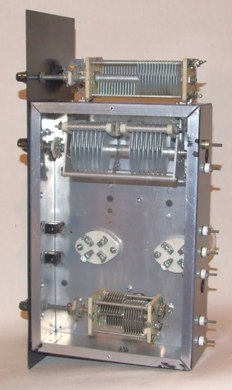
With the chassis and front panel drilled, punched and painted this project should start looking more like a kit. Everything is in hand, all I need to do is mount, wire and solder.

I laid out the chassis and front panel so that eventually this amplifier will serve as an upper deck of a 70 watt CW transmitter. My 1934 transmitter will be the lower deck/driver.

Friday, March 5, 2010

More RF Amp


A push-pull amplifier is two tuning caps, two coils and two tubes right? With all of the support circuitry, the output loading circuit I like and miscellaneous parts and hardware it is starting to look like a real project. Once the drilling is done this one will sit until warm weather returns to Minnesota (maybe May?). I want to paint the chassis but not with snow on the ground and temperatures in the 30s.

Sunday, February 21, 2010

RF Amp


Most of my 30s vintage transmitters are in the 10-20 watt range. It would be fun to have a little more power, especially with my 10 watt Meissner Signal Shifter / VFO. According to the specs two Taylor TZ20s in push-pull can be driven with 5 watts to about 110 watts input or 85 watt output. This sounds like what I'm looking for.

As usual any project starts with sorting through parts and then doing a preliminary layout before taking a drill to the metal.