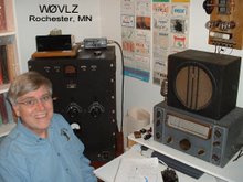
To see if I'm on the air right now click here
Showing posts with label 1934 transmitter. Show all posts

Friday, September 20, 2019

FB7 / Parallel 46s Station On the Air

This week I finally finished up my early 30s CW station using a National FB7 and a homebrew 1934 transmitter. To-Dos that have been slowing me down are recapping the FB7, making a new power cable (and repairing the FB7 power cable) and then shoe horning everything into the corner I  have available for it. Does anyone else have a shack that reminds them of the old advertising slogan: "There's always room for Jello"?

I got on the air looking for signal reports and  RBN feedback. I had three QSOs that night (N4EDE/NC, W9BRD/NJ, W5RG/FL). All reported that my 10 watts sounded fine. W9BRD, even gave me a "first rate note" comment. 27 hits on the RBN said I was also getting out. Great! I've another fun station to put on the air and it is a perfect match for the January 2020 AWA Linc Cundall CW Contest.

What next? The AWA Bruce Kelley1929 QSO Party is coming up in November. I better get my  Push Pull Colpitts transmitter back on line, tested and ready to go.

Wednesday, September 19, 2018

Winter 2018-19 Boat Anchor Season

As summer wraps up here and turns into fall I start shifting from QRP-In-The-Park to Boat-Anchors-In-The-Basement and the winter contest/operating event season. One station in the works here is a moderate capability mid 30s CW setup using a couple of TZ-20s (at about 50 watts) in the final and a National FBX-A receiver. It qualifies nicely for the AWA Linc Cundall Memorial CW Contest.

I've now finished up the transmitter power supply so I'll soon be testing it out on the air. The transformer is rated for 560V at 270mA so should certainly easily handle my 50-70W transmitter. At 31 pounds, mostly iron, I don't plan to move this one around much.

Next on the to-do list is to go through the FBX-A getting it on the air.

Friday, November 25, 2016

Thanksgiving Day Power Supply

After Thanksgiving Dinner this year I took the opportunity to make progress on the power supply for my 1939 transmitter.

I completed the  500 VDC and 7.5 VAC sections needed for the amplifier.  PSU Designer II indicated that I needed to allow for almost 2000 volts across each of the diodes in the bridge rectifier. I ended up using two 1000 PIV diodes in series for each leg of the bridge. This is a boat anchor power supply with silicon hidden under the chassis. It needed some glow. I added a type 80 rectifier connected only to 5 VAC so that it would look right. After all, real radios need to glow in the dark.


Eventually I'll add components to power the oscillator/buffer stage including 250 VDC, 150 VDC and 2.5 VAC. In the meantime I can drive the amplifier with either my Utah Jr or Meissner Signal Shifter.

Monday, January 20, 2014

AWA Linc Cundall Memorial OT CW Contest

Between 80 and 40 I managed twelve contacts using my National HRO Sr and TZ-20 transmitter with a low hung inverted L antenna. By contesting standards not a lot but still better than any of my LC QSO counts going back 20 years.

I worked nothing to the west but I did manage Qs to Canada, the east coast and southwest. I heard N2BE a lot. Too bad I could only work him once per band. I was surprised to not hear many of my MN friends on the air. Of the eight I worked in the BK I only heard three on for the LC.

I have grown to depend on the Reverse Beacon Network to help me decide if the band is dead. If I call CQ and I don't get a lot of feedback from the RBN with reasonable signal strength it's time to change bands or go to bed.

Friday, November 15, 2013

More about a power supply for a 1939 Transmitter

Plans change....after studying my collection of available transformers I found one rated at 560 (center tapped) at 270mA. This would work well with a full wave bridge rectifier as the TZ-20 final stage B+ (550VDC). Half of this, full wave center tapped rectified, is about right for the buffer stage (270VDC) and a VR-150 should be able to take this down to 150V for the oscillator stage.

I recalled Brian, WA7PAC's, comment to me several years ago when I was
dealing with a similar problem on a different transmitter. He suggested an "Economy Power Supply". Rather than clone my one transformer it's possible to run it with both a full wave bridge rectifier and a full wave center tapped rectifier.This looks like it may work.

I'm using PSU Designer II to help me play with filter options before I put solder to the iron.

Wednesday, November 13, 2013

A power supply for a 1939 Transmitter

With my KX3 n the shop because of a bad output transistor and cool weather returning to SE Minnesota I'm again in the basement looking at boat anchor projects. One project on my list is to clean up the power supply for my 1939 transmitter. Right now I've borrowed the power supply from my 1951 novice station to power the oscillator/buffer stages and used a second 500VDC supply for the TZ-20 amplifier stage. Needless to say, these don't show up in my blog photos of the transmitter.

My new power supply is a pretty brute force design delivering 550VDC, 300VDC and 150VDV to the transmitter using two power transformers, a couple of 5R4 rectifiers, a VR-150 and the needed filtering circuits. It will be two fairly heavy supplies on one chassis.

I found all of the transformers and components in my junque box but not a stout enough chassis for all of the iron. I turned to my slat board design to take care of this shortage.


Tuesday, September 22, 2009

More 1934 Transmitter

Remember the safety problem with my 1934 transmitter? Two of the phone plugs is for metering and the third is for the key. If, in the heat of the moment, I get the them mixed up and plug the key into a B+ metering jack, I'll have up to 300 volts on the key.

To protect myself I tied a length of string and a plastic cable clamp to the key phone plug (any lump of plastic would work). After the key is plugged in I slide the cable clamp under the front edge of the transmitter. The string is short enough that the plug can not be removed without getting the clamp out from under the transmitter.

Wednesday, September 16, 2009

A 1934 transmitter - On the Air

Yesterday I set up my 1934 transmitter up with my NC101X and tried the pair out on 80 meters using my endfed 105' inverted "L" antenna only about 10'-20' off the ground. The station worked fine.

At 21:45 I had a nice QSO on 3570 with NG9D in Plainfield, IL. Lynn's signal varied from 589 to 599+. He reported that my 589 signal sounded fine/stable.

Also shown in the picture is my iambic keyer set up to key older tube rigs.

Sunday, September 13, 2009

More 1934 transmitter - It Works!

I've finished wiring my 1934 transmitter, powered it up and it works! With about 300 volts on the plates of the 46s and the 47 it loads to 15-20 watts input and 7-10 watts output. It sounds great also.

One change I made from the Bill Orr design is to connect the 47 screen to regulated 150V rather than a resistor network off of B+.

This transmitter is not without some personality, though. Only the amplifier stage is keyed so the oscillator stage runs continuously. On key up any energy from the oscillator that makes it to the antenna will be heard as a faint back wave. We'll see if this is objectionable. The second personality trait is, unfortunately, pretty nasty. When using the rig, two phone jacks are for metering plate current and the third is for the key. If in the heat of the moment I get the three mixed up and plug the key into a metering jack I'll have over 300 volts on my key. To make matters even worse, keying the metering/B+ line works so I may not even be aware of what I've done until I get myself between the key and ground. I'm planning something that will keep me from accidentally removing the key plug.

Eventually I plan is to mate this transmitter with my National FB7X for a complete 1934 station that I'll use in the 2010 AWA Linc Cundall OT CW Contest.

Thursday, July 9, 2009

More 1934 Transmitter


I've gotten the components all mounted and the transmitter is ready for wiring. I learned a few things along the way...

30s vintage Sangamo mica capacitors are large enough that they don't mount well on their own leads. Each one must be mechanically supported, either by a solder strip or by screwing to the wooden sides of the chassis.

The wooden chassis takes 1 1/2 inches of available length and width. This can impact the layout. Using an all metal chassis there is space for a buffer stage between the oscillator and amplifier. With 1 1/2 taken off the length/width plus the added reinforcing across the middle it would be a challenge to fit the buffer stage in there.

Will the lead length be a problem? Certainly I wouldn't trust this spread out layout at 30MHz but it may be OK on 7MHz. Time will tell.

Sunday, May 31, 2009

More 1934 Transmitter

After some quality table saw time, a bunch of drill press time and eight coats of paint (primer coat, satin black, three coats of wrinkle paint that didn't wrinkle and three more coats that did) I have a wood and aluminum chassis that looks pretty good. The layout is much like the Gross CW-25 but without the buffer stage. In place of the middle/buffer tuning dial I'm mounting a plate current meter. Across the bottom are three 1/4" phone jacks. One is the key jack. The other two are in the B+ circuits of the oscillator and final amp stages. These two jacks will have 350VDC exposed on the outside rim. For safety I recessed these jacks 1/2" behind the front panel. I also added a B+ switch on the far right.

I found two more examples of this tube lineup. One is a George Grammer construction project covered in November 1932 and February 1933 QST. The second is the Collins 4A transmitter.

Friday, April 10, 2009

More 1934 Transmitter


After collecting all of the parts comes "playing checkers" to find the best layout given the set of parts located. In this case I found suitable 30's parts for all of the major components except the chassis itself. For it I'm using a 17"x10" sheet of 18 gauge aluminum. It will be fastened to a 4 1/2" tall wooden frame and then frame and aluminum painted black winkle.

Thursday, April 9, 2009

A 1934 Style Transmitter

Since the AWA Linc Cundall OT CW Contest in January I've been thinking about building another transmitter, this one falling in between my 1929 TNT transmitter and my Thordarson 100 or late 30's 6L6 transmitters. I want to use it with my National FB-7 so it needs to be an early to mid 30's design.

A popular design in the early 30's used a type 47 as a crystal oscillator driving a buffer and final on 160 through 10 meters. Typical power was anywhere from 20 watts on up depending on the tube lineup. The Gross CW-25 was one example. It had a 47 oscillator driving a 46 buffer/multiplier followed by two 46s in parallel. Plug-in coils were available for all bands 160 - 10. This looks like a pretty neat transmitter. More about the CW-25 can be found in Bill Orr's "Antennas" column in the February 1977 issue of CQ magazine.

I wish I could find a CW-25 available. Does anyone have one they will part with? In the mean time I'll have to homebrew something.

The cover story of the November 1971 issue on CQ magazine is a Bill Orr construction article describing a 160/80/40 meter "1934 Style Transmitter". Circuit-wise it is a close match to the CW-25 but without the buffer/multiplier stage. This circuit design fits my early/mid 30's requirement but the CW-25 chassis sort of construction better matches the "modern" look of my FB-7. I'll combine the two using the circuit from Bill Orr's article but building it to look more like the CW-25.

Notice that the schematic scanned from the original CQ article is missing the connection between the coupling capacitor C6 and the 46 tube grids.