I've tweaked on my 1T4/3V4 regen receiver a little more. (Better headphones for more audio and fixed the bandspread dial slippage/backlash). It is now working pretty good. Here's a little demo video:
Showing posts with label Regen. Show all posts
Showing posts with label Regen. Show all posts
Monday, September 7, 2015
Saturday, September 5, 2015
1T4 / 3V4 Regenerative Portable - continued

I've finished my 1T4 / 3V4 Regenerative Portable. Along the way I found Dave's "Regenerative Tube Radio Building Notes" at http://makearadio.com/misc-stuff/regennotes.php . Dave condenses down to a few pages a lot of the information that you need to know about regen receiver design/options without spending a lot of time on theory. It fits his philosophy of "No big theory discussions or math here. You are here to build a radio, not to earn your college degree." This was helpful as I made design changes to fit parts available.

Next, the original design from Bob's Data had both low and high impedance outputs. I'm only using high impedance headphones so I replaced the 10K to 8 ohm output transformer with a 3:1 inter-stage coupling transformer. I had also hoped transformer coupling to my headphones would increase the volume...that didn't happen. More on this later.
I also decided to add an antenna coupling control. I'm not certain this helps a lot but it may come in handy when connected to a long/resonant antenna.
Finally, all of Dave's feedback control options show an RF choke in the B+ line going to the tickler coil. This seemed like a good idea. It keeps the feedback RF all at the coil rather than wandering around the chassis.
Bob's design information included coil winding documentation. I had a set of pre-wound 1930's vintage Hammarlund 6 pin shortwave coils. I used these rather than wind my own coils.

 The final radio looks good and nicely covers 80 and 40 meters. I have several sets of high impedance headphones that I've acquired over the years. My Neufeldt & Kuhnke Model D headphones gave the best volume. This is a battery set designed for A/filament voltage from a flashlight
battery and B+ from a series of 9V batteries. I used my 20s battery set
power supply from Antique Electronic Supply. This power supply provides the regulated A and B voltages that I needed. See https://www.tubesandmore.com/products/K-101A .
The final radio looks good and nicely covers 80 and 40 meters. I have several sets of high impedance headphones that I've acquired over the years. My Neufeldt & Kuhnke Model D headphones gave the best volume. This is a battery set designed for A/filament voltage from a flashlight
battery and B+ from a series of 9V batteries. I used my 20s battery set
power supply from Antique Electronic Supply. This power supply provides the regulated A and B voltages that I needed. See https://www.tubesandmore.com/products/K-101A . I'm a little disappointed in performance but this is a 1940s/1950s starter set. Maybe this is a good as it gets. Volume is low and the regeneration setting is tricky. When regeneration is set for maximum sensitivity I feel like I'm riding the crest of a wave. Any move may send the set out of CW regeneration or hurt sensitivity. What I'm seeing may be because of the tickler winding. Most references I've found indicate that the correct regen pot setting is at about 12:00. Mine is closer to 9:00...the screen voltage (and, consequently, the 1T4 gain) is pretty low when CW regeneration kicks it. Is this a problem? I don't know. The plate voltage is still the same. I'll have to wind a coil and play with the tickler winding to find out. The other limitation I found was antenna loading impact on the received frequency. Changing my antenna trimmer setting changed the frequency a lot. The solution was to add an RF stage. This won't happen. Once the C1, the bandset capacitor, is set I leave the antenna trimmer alone.
Saturday, August 8, 2015
1T4 / 3V4 Regenerative Portable - continued
 After time with chassis punches, drill press, files, nibbler .... I've gotten my chassis finished and the major components installed. The bandset and band tuning capacitors are each mounted an inch above the chassis to allow space for the National type K dial.


Solder is next.
Thursday, July 9, 2015
1T4 / 3V4 Regenerative Portable
 Since getting a 3S4 QRP midget transmitter I've been thinking about building a receiver to match it. I wanted to use tubes along the same lines as the 3S4 and, at the same time, have a late 50s style. The late 50s/early 60s ARRL "How to Become a Radio Amateur" featured a two tube regen with a 3 1/2" National type K dial. That sort of style was what I was looking for.
 I've found the parts I need and have played with them to figure out a layout I like. The chassis is marked up and I'm ready to drill.
| Parts List (use 1/2 watt resistors): | R1 1 Meg R2 39K R3 100 K Potentiometer R4 47K R5 2 Meg Potentiometer R6 47K C1 11-194 pF Variable (7 full plates) C2 9-19 pF Variable (one ¾ inch diam. plate) C3 100 pF C4 .002 uF C5 .01 uF |
C6, C9 1 uF @ 100V C7 .05 uF C8 .22 uF L1,2,3 Wound on same PVC form T1 10K to 8 ohm Audio Transformer |
Tuesday, July 7, 2015
A Ross Hull Three Tube Regen
 A couple of weeks ago I spotted a radio on ebay that looked really interesting. I've been doing some research on it since then.
 This radio is a three tuber with a tuned RF stage, regenerative detector and a single stage of audio ... not unusual for an early 30s shortwave set except for the mechanical layout. All of the tubes are mounted horizontally with the RF tube projecting through the RF/Detector stage shield. This layout allows for a compact set. The National SW3, for example, is a three tube regen with a tuned RF stage. It measures 9.5"x7"x9". This set is only 7"x5"x6.5", less than half the size of the SW3.
A search found the original described in the June 1931 issue of QST. Ross Hull designed this set to demonstrate the capabilities of the new type 33 audio pentode. He bragged about the gain of the AF stage and being able to drive a speaker to good volume. Why, then, didn't he include a volume control? You have to detune the RF stage if a station is too loud. Along the way, though, Hull did, in typical Hull style, came up with the clever mechanical layout. Hull was also an early VHF advocate/experimenter. This layout allows fairly short leads. I have to wonder if he was thinking ahead to 60MHz when he sat at the drawing board designing this radio.
Thursday, June 10, 2010
The Mitey Mite Beginner Transceiver
Last weekend I attended the TwinsLAN/3M swapmeet in St Paul, MN. This is always one of my favorite swapmeets of the year. It is open-air in a large parking lot so all of the boatanchors show up that we don't want to lug inside to a table...just throw open the van doors or uncover the pickup bed and sell.This year I saw many more boat Nationals, Hallicrafters, Johnsons and Heathkits than I've seen in the past...it was a great meet.
One item caught my attention, a late 40's United Surplus Materials "Mity Mite" HF radio. It is a three tube regenerative receiver/transmitter. The audio stage of the two tube receiver doubles as a single tube crystal controlled oscillator/transmitter. The third tube is a rectifier. I bought it from KB0DVM. He built and used this little rig while he was an Ag student at U of Wisconsin/Madison in 1948.
This is a great example of a minimal design making use of available WWII surplus parts. The first steps in the instruction manual explain how the disassemble the included BC-745 pogo stick transceiver tuning unit to get the crystal, two sockets, a tuning coil and the bandset capacitor. The design itself would not make it off of today's drawing boards. First it is an AC-DC set with one side of the AC line connected directly to the metal chassis/cabinet...what a shocker! A safer (and more expensive) AC-DC design has circuit ground isolated from the chassis but not this one. A quick look at the operating instructions shows a note about not connecting an antenna ground but nothing about the shock hazard. Next there is no tuned circuit in the transmitter output. Any harmonics generated by the crystal oscillator are passed unattenuated to the antenna. Again not a good design but it works, though on several bands at the same time.
The Mity Mite is a pretty neat little radio that reflects the time and market it was designed for. It is a keeper. I'll probably figure out a way to put it on the air (while staying on one band and not killing myself).
 up that we don't want to lug inside to a table...just throw open the van doors or uncover the pickup bed and sell.This year I saw many more boat Nationals, Hallicrafters, Johnsons and Heathkits than I've seen in the past...it was a great meet.
One item caught
 my attention, a late 40's United Surplus Materials "Mity Mite" HF radio. It is a three tube regenerative receiver/transmitter. The audio stage of the two tube receiver doubles as a single tube crystal controlled oscillator/transmitter. The third tube is a rectifier. I bought it from KB0DVM. He built and used this little rig while he was an Ag student at U of Wisconsin/Madison in 1948.
This is a great example of a minimal design making use of available WWII surplus parts. The first steps in the instruction manual explain how the disassemble the included BC-745 pogo stick transceiver tuning unit to get the crystal, two sockets, a tuning coil and the bandset capacitor. The design itself would not make it off of today's drawing boards. First it is an AC-DC set with one side of the AC line connected directly to the metal chassis/cabinet...what a shocker! A safer (and more expensive) AC-DC design has circuit ground isolated from the chassis but not this one. A quick look at the operating instructions shows a note about not connecting an antenna ground but nothing about the shock hazard. Next there is no tuned circuit in the transmitter output. Any harmonics generated by the crystal oscillator are passed unattenuated to the antenna. Again not a good design but it works, though on several bands at the same time.
The Mity Mite is a pretty neat little radio that reflects the time and market it was designed for. It is a keeper. I'll probably figure out a way to put it on the air (while staying on one band and not killing myself).
Monday, May 24, 2010
An SW-4 Mystery
A friend of mine noticed that my National SW-4 shown  at http://www.prismnet.com/~nielw/nat_list/sw4.htm uses what looks like standard SW3 type audios as opposed to the National "Duo Cou
 pler"
pler"  mentioned in the SW-4 ad. Other National radios show a production process that used parts that were available. Close inspection and comparisons between National receivers of the same model can show undocumented differences in details. Are this audios replacement parts or do they reflect a production change to take advantage of existing stock?
As I looked at these audios I saw something else. Close inspection of my SW-4 bakelite chassis showed three large plugged holes and several plugged small bolt holes. Parts mounting and the quality of the work makes it appear that all of this chassis rework was done before most of the parts were mounted. Why all of the extra plugged holes? Was the chassis originally drilled for another product and then reworked? Was the chassis made from a piece of bakelite that already had a few holes in it? Did a worker make several errors that had to be fixed before the chassis could be used?
There are a few SW-4s still around. I wonder, do they show similar changes and reworks? Were these sorts of production techniques common or is this really a set that was carefully reworked at some point after it left the factory?
 at http://www.prismnet.com/~nielw/nat_list/sw4.htm uses what looks like standard SW3 type audios as opposed to the National "Duo Cou
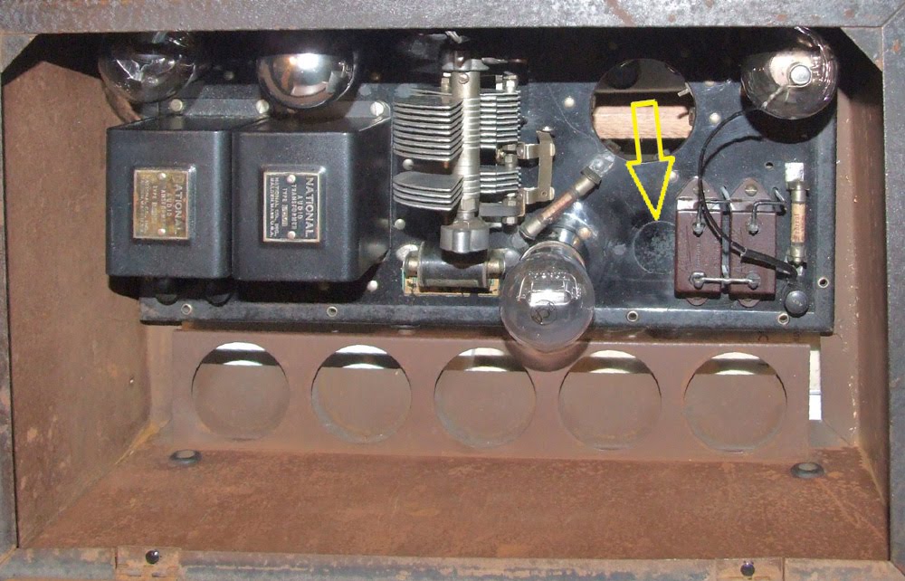 pler"
pler"  mentioned in the SW-4 ad. Other National radios show a production process that used parts that were available. Close inspection and comparisons between National receivers of the same model can show undocumented differences in details. Are this audios replacement parts or do they reflect a production change to take advantage of existing stock?
As I looked at these audios I saw something else. Close inspection of my SW-4 bakelite chassis showed three large plugged holes and several plugged small bolt holes. Parts mounting and the quality of the work makes it appear that all of this chassis rework was done before most of the parts were mounted. Why all of the extra plugged holes? Was the chassis originally drilled for another product and then reworked? Was the chassis made from a piece of bakelite that already had a few holes in it? Did a worker make several errors that had to be fixed before the chassis could be used?
There are a few SW-4s still around. I wonder, do they show similar changes and reworks? Were these sorts of production techniques common or is this really a set that was carefully reworked at some point after it left the factory?
Sunday, May 6, 2007
A mid 30's Three Tube Regen

I aquired another radio last week. This one I "won" through ebay. The pictures posted on ebay showed a fairly ughly set with three mis-matched dials. The layout, though, suggested the "Three Tube Regenerative Receiver of Unusual Performance" by George Grammer and written up in the January 1933 issue of QST.


I bid and the gamble paid off. Underneath the flaking paint front panel and cabinet was a fairly nicely done version of George Grammer's design.


George grammer's original article was more than another construction project. He spent a large part of the article talking about features of good regen receiver design before describing "a practical receiver". This receiver includes a tuned RF stage and general coverage/bandspread tuning. Bandspread tuning is via the drum dial at the left after the detector and RF stage bandset capacitors are set. The receiver showed up in the ARRL handbooks through 1937.
Subscribe to:
Posts (Atom)

