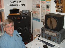
A push-pull amplifier is two tuning caps, two coils and two tubes right? With all of the support circuitry, the output loading circuit I like and miscellaneous parts and hardware it is starting to look like a real project. Once the drilling is done this one will sit until warm weather returns to Minnesota (maybe May?). I want to paint the chassis but not with snow on the ground and temperatures in the 30s.
Friday, March 5, 2010
More RF Amp
A push-pull amplifier is two tuning caps, two coils and two tubes right? With all of the support circuitry, the output loading circuit I like and miscellaneous parts and hardware it is starting to look like a real project. Once the drilling is done this one will sit until warm weather returns to Minnesota (maybe May?). I want to paint the chassis but not with snow on the ground and temperatures in the 30s.
Sunday, February 21, 2010
RF Amp
Most of my 30s vintage transmitters are in the 10-20 watt range. It would be fun to have a little more power, especially with my 10 watt Meissner Signal Shifter / VFO. According to the specs two Taylor TZ20s in push-pull can be driven with 5 watts to about 110 watts input or 85 watt output. This sounds like what I'm looking for.
As usual any project starts with sorting through parts and then doing a preliminary layout before taking a drill to the metal.
Friday, February 5, 2010
1929 and 1930 Stations
Lots of times questions get asked about what sort of rig to put on the air as a 1929 station. What were hams really using? Do the back page ads in QST really reflect what was on the air?
As I went through my old issues of the AWA OTB/Journal I found Bruce Kelley's comments on 1929 equipment in the May 1994 issue. He summarized 1929 and 1930 QSL card information from W1NE. He saw that Hartley oscillators and the 210 dominated the transmitter scene and almost 90% of the receivers had no RF stage. I found two 1930 QSL cards in my collection and added those to Bruce's tabulation. I've posted this data at http://www.prismnet.com/~nielw/OldQSLCardInfo2.pdf .
If you have similar 1929 or 1930 QSL data email it to me and I'll add it to the summary.
As I went through my old issues of the AWA OTB/Journal I found Bruce Kelley's comments on 1929 equipment in the May 1994 issue. He summarized 1929 and 1930 QSL card information from W1NE. He saw that Hartley oscillators and the 210 dominated the transmitter scene and almost 90% of the receivers had no RF stage. I found two 1930 QSL cards in my collection and added those to Bruce's tabulation. I've posted this data at http://www.prismnet.com/~nielw/OldQSLCardInfo2.pdf .
If you have similar 1929 or 1930 QSL data email it to me and I'll add it to the summary.
Monday, January 25, 2010
AWA Linc Cundall Memorial OT CW Contest
For two days this past week I participated in the AWA Linc Cundall Memorial OT CW Contest. This contest gives a significant multiplier to those using pre 1947 gear. I used a National NC-101X and one of my recent homebrew transmitters, a "46 job". I worked nine stations in four states plus Ontario.
Saturday, January 2, 2010
Photo QSL Cards
QSL cards are a ham radio tradition that I was introduced to when I was a novice in 1966. My novice card then was a fairly generic design ordered 100 cards at a time from the Little Print Shop near Austin, Texas.
These days I usually custom create my QSL cards to go with a particular event or location. Lots of places will print digital photos and most allow on-line submission. I've seen prices as low as 9 cents per print with no minimum. All that is needed is a jpg file the right size.Start with your favorite graphics editor, even Microsoft Paint has enough power and function to do the job.
First create a blank colored background with the right aspect ratio to match the prints to be ordered. I planned to order 4" x 6" prints so I created a 800 x 1200 pixel background. This background gives you control over auto resize/crop that occurs when your file is printed. The color doesn't matter. It will eventually get trimmed off.
Use your editor to cut out from the middle of the background a rectangle the matches the final size of the QSL card. For a typical 3.5" x 5.25" QSL card on a 800 x 1200 pixel background this rectangle will be 700 x 1050 pixels. This space is where you create your QSL card.
Use your graphics editor to add whatever QSL card text and images you wish. For Microsoft Paint I found it best to crop and resize any photos or images before I paste them into the QSL card.
Send the jpg file off to be printed.The resulting 4" x 6" print will have a colored frame that needs to be trimmed off. This should leave your 3.5" x 5.5" QSL card. A paper cutter works great for trimming.
Other cheaper options may be available but for the QSL card information I use a Avery #5264 3.25" x 4" shipping label stuck to the back of the QSL card. Inside the Avery box are instructions telling how to use a template included in Microsoft Word to create six preprinted labels per sheet of shipping labels.
Sunday, December 13, 2009
1928 Hartley / AWA 1929 B Kelley QSO Party
The past two weekends gave me a chance to get some more operating time on my 1928 Hartley transmitter. These were the weekends of the AWA Bruce Kelley Memorial 1929 QSO Party . The first weekend I used my HRO Sr with the Hartley. On the second weekend I paired my Drake 2B with my Hartley. I had a good time working other '29 transmitters in Minnesota, Wisconsin, Illinois, New Hampshire, North Carolina, Ohio, Ontario and British Columbia.
In total I made 16 contacts and learned a little about the limitations of my station. First, I really need a higher antenna. My antenna is a 105' inverted "L" only about 10' to 20' off the ground. It loads up nicely but, given t
his low height, has a fairly high angle of radiation. It probably qualifies as a Near Vertical Incident Skywave (NVIS) Antenna. Out of my first six contacts, five were here in Minnesota and most of them reported a strong signal. I also found that the best time was late afternoon, not the night time hours. The first weekend the only QSO I had outside of MN was with Ohio and it was when the QSO Party rules allowed me to crank the power up a little. When the propagation changes my antenna works OK but I feel it does limit me. Next, I learned that 40 meter transmitter performance is a little down from 80. While I've received a good signal report on 40, I can't get as much power out and I had more trouble getting on frequency. My Hartley is a usable 40 meter transmitter but 80 is definitely its better band.

In total I made 16 contacts and learned a little about the limitations of my station. First, I really need a higher antenna. My antenna is a 105' inverted "L" only about 10' to 20' off the ground. It loads up nicely but, given t
Monday, November 16, 2009
1928 Transmitter Tuning
Ross Hull's QST article documents a lot of experimentation done to understand the behavior of self-excited oscillators. Whether Hartley, Colpitts, TPTG or TNT Hull concluded that all of them behave about the same and the same tuning guidelines apply to all of them. In summary, any self-excited oscillator should be run at only about half power in order to produce at acceptable signal.
After the transmitter is on frequency and running at full plate voltage:
1) Tighten the antenna coupling as much as possible. In the case of my transmitter this meant moving the antenna coil until it almost touched the tuning coil. At maximum antenna coupling tune antenna loading for maximum output and note this "maximum output".
2) Back off antenna coupling to 75% maximum power (watts) or 85% output current (RF Amps) retuning antenna loading along the way.
3) Once you are at 75% power (or 85% RF current) output, detune antenna loading by adding capacitance to reduce output another 75% power (or 85% RF current). After detuning check your signal. In some cases Hull found that detuning antenna loading worked best if capacitance was reduced rather than added.
Hull plotted frequency vs load capacitance. His curves show a fairly steep curve around resonance and then they flatten out. When a self-excited oscillator is peaked up for maximum output any changes in antenna loading will have a maximum impact on frequency. At this tuneup point an antenna swaying in the wind (changing the load that the transmitter sees) will have a maximum impact on the signal frequency. Detuning the output the oscillator away from peak output moves the operating point to the flatter part of the frequency vs load capacitance curve. Antenna sway will have less impact.
After the transmitter is on frequency and running at full plate voltage:
1) Tighten the antenna coupling as much as possible. In the case of my transmitter this meant moving the antenna coil until it almost touched the tuning coil. At maximum antenna coupling tune antenna loading for maximum output and note this "maximum output".
2) Back off antenna coupling to 75% maximum power (watts) or 85% output current (RF Amps) retuning antenna loading along the way.
3) Once you are at 75% power (or 85% RF current) output, detune antenna loading by adding capacitance to reduce output another 75% power (or 85% RF current). After detuning check your signal. In some cases Hull found that detuning antenna loading worked best if capacitance was reduced rather than added.
Hull plotted frequency vs load capacitance. His curves show a fairly steep curve around resonance and then they flatten out. When a self-excited oscillator is peaked up for maximum output any changes in antenna loading will have a maximum impact on frequency. At this tuneup point an antenna swaying in the wind (changing the load that the transmitter sees) will have a maximum impact on the signal frequency. Detuning the output the oscillator away from peak output moves the operating point to the flatter part of the frequency vs load capacitance curve. Antenna sway will have less impact.
Sunday, November 15, 2009
1928 Transmitter Signal Quality
Ross Hull's August 1928 QST article, "Overhauling the Transmitter for 1929", is a great article for anyone interested in putting a late 20s/early 30s self excited oscillator on the air. This includes the Hartley, Colpitts, TPTG and TNT transmitters used in the AWA Bruce Kelley 1929 CW Party. In the words of QST, this "is, we feel, one of the most important articles ever published for the radio amateur. Let every amateur study it most carefully, and apply its information, for it contains salvation for 1929." It can be found by searching the QST magazine article archives at http://www.arrl.org/.
Ross Hull's major point is that the poor signals legal in 1928 will no longer be acceptable in 1929. He further states that the main problem is the "men pushing the keys". How 1929 transmitters are tuned up makes a big difference in signal quality. The actual transmitter required to meet 1929 standards can be fairly simple. To prove his point he describes the one I built, a "simple -- in fact crude -- rig...capable of performing quite creditably". He even goes on to say that he anticipates some "raspberries" over the crudity of his simple transmitter.
Transmitter features helping signal quality include a heavy tank coil/circuit, mounting the tube so tuned circuit heating is minimized and high tuning capacity/low inductance. Ross Hull emphasizes that the inexpensive hardware features he's listed combined with proper tuning over come lots of the frequency shift introduced by marginally filtered or unregulated B+ supplies, antennas swaying in the wind and components heating up. Simple 1929 transmitters don't need to "splutter, wobble, creep and rattle across great slices of the bands".
In fairness, I still find that moderate winds causing antenna sway does introduce some FMing, but my signal is acceptable. Hull, in fact, states that a DC (T9) note is extremely uncommon and rather unpleasant. He much prefers a more "musical note" that we might rate T8. Given proper tuning that's about where mine is: a sweet, musical, T8 signal. Also keep in mind that this transmitter design does not address other "creature comforts". It is microphonic requiring it to be placed on a table separate from the operating position, hand capacity is a problem and bandspread, such that there is, is barely adequate for getting on frequency. These could be addressed in a more expensive design but their solution is not required in order to archive "any reasonable [signal quality] standard set for 1929".
Ross Hull's major point is that the poor signals legal in 1928 will no longer be acceptable in 1929. He further states that the main problem is the "men pushing the keys". How 1929 transmitters are tuned up makes a big difference in signal quality. The actual transmitter required to meet 1929 standards can be fairly simple. To prove his point he describes the one I built, a "simple -- in fact crude -- rig...capable of performing quite creditably". He even goes on to say that he anticipates some "raspberries" over the crudity of his simple transmitter.
Transmitter features helping signal quality include a heavy tank coil/circuit, mounting the tube so tuned circuit heating is minimized and high tuning capacity/low inductance. Ross Hull emphasizes that the inexpensive hardware features he's listed combined with proper tuning over come lots of the frequency shift introduced by marginally filtered or unregulated B+ supplies, antennas swaying in the wind and components heating up. Simple 1929 transmitters don't need to "splutter, wobble, creep and rattle across great slices of the bands".
In fairness, I still find that moderate winds causing antenna sway does introduce some FMing, but my signal is acceptable. Hull, in fact, states that a DC (T9) note is extremely uncommon and rather unpleasant. He much prefers a more "musical note" that we might rate T8. Given proper tuning that's about where mine is: a sweet, musical, T8 signal. Also keep in mind that this transmitter design does not address other "creature comforts". It is microphonic requiring it to be placed on a table separate from the operating position, hand capacity is a problem and bandspread, such that there is, is barely adequate for getting on frequency. These could be addressed in a more expensive design but their solution is not required in order to archive "any reasonable [signal quality] standard set for 1929".
Friday, November 13, 2009
1928 Hartley Coils

Pictured are my 80 and 40 meter tank coils. Ross Hull made a strong point in his QST article that these coils need to be able to handle a lot of current (5 amps of RF for this design), be mechanically stable and tune with as much capacitance as possible.
These coils were wound out of 1/4" OD copper tubing. A piece of 2 3/8" OD pipe was used for a winding form. Once a coil was wound I installed it and then adjusted the turn spacing so that the bottom edge of each band fell close to maximum tank tuning capacity.
While shopping for copper tubing I found that tubing wall thickness varied brand to brand. For best current handling and mechanical stability I bought the heaviest/thickest I could find.
Friday, November 6, 2009
More 1928 Hartley
T
he last few evenings have included some final cleanup of the Hartley and then getting it on the air some more. There's been several of us on 80 meters around 3615 during the late evening but the 80 mtr propagation god hasn't smiled on me since my QSO with VE3AWA. Some of the others have heard me but I haven't worked anyone. Hear is how I sounded last night at VE7SL's QTH in British Columbia
by clicking here.
Subscribe to:
Posts (Atom)