After building a
1T4/3V4 regen receiver to go with
my 3S4 QRP Midget I decided that I needed to rebuild the Midget. What I'm ending up with is more like a Midget on steroids. It still uses two 3S4s in parallel and runs on 90 VDC but it now fits better with the 1T4/3V4 regen. With matching knobs and paint the two will be my mid 50s QRP-in-the-Park Twins.

I'm making several changes from the original QRP Midget. Since I wanted to run this transmitter and my regen from the same power supply I'm rewiring the filaments for 1.5 VDC rather than 6 VDC. Next, the QRP Midget directly heated 3S4 cathodes require a floating filament supply in order to be keyed. I couldn't share the filament supply between the regen and the transmitter. My fix is to key the 90 V B+ line. I have a WWII key with totally enclosed contacts so I won't find myself across 90V to ground sometime. Next I added an antenna loading control. Given the parts I had and the mid 50s sort of design a pi network made the most sense. Dip and load pi network tuning works best with a plate current meter so I also added that. Finally, I saw no need for the QRP Midget DPDT power switch. I left it out completely. I'll just disconnect the filament supply instead. The original QRP Midget fit in a small Bud minibox. Mine will require a 4x6 chassis.
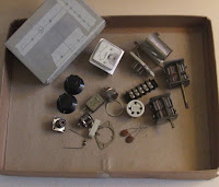
I've found all of the parts and
laid out the chassis. Next step is to drill...I'm committed then.


1 comment:
Hello Neil
What is the value of variable capacitors?
How many winding I need to make the coil?
Post a Comment