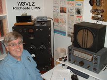
I've finished my mid 50s QRP-in-the-Park Twins. Today I put them together and got on the air....unfortunately no responses to my CQs, but my 1 watt signal was getting out.
Thursday, March 24, 2016
3S4 x 2 Transmitter (On the Air)
I've finished my mid 50s QRP-in-the-Park Twins. Today I put them together and got on the air....unfortunately no responses to my CQs, but my 1 watt signal was getting out.
Tuesday, March 22, 2016
3S4 x 2 Transmitter (Wired)
I've finished wiring my new transmitter. To help debug a little I did use three colors of wire; black for the ground and cathode circuits, green for the signal grid and red for the plate and screen circuits. Recommended in the 50s was solid (not stranded) wire and square corners with wires running parallel to the chassis sides. The wiring certainly came out looking better than some of my other projects but lead lengths may be a problem if I try this at higher frequencies.
This transmitter sounds fine and per spec it loads up to about a watt out on 40. I'll need to add more capacity for the pi network to work well on 80.
Fortunately I still have my winter vertical up and tomorrow's forecast is for 8"-12" of snow here in SE Minnesota. I'll have time to be on 40 trying out my 3S4 x 2 - 1T4 / 3V4 Regen station.
Friday, March 18, 2016
3S4 x 2 Transmitter (Ready to Wire)
The paint is dry and it looks good. The parts all mounted with no problems. Wiring is next.
Looking at the actual underside vs my drawings it looks a lot tighter than I had imagined...but, fortunately, only half a dozen or so components need to be wired in under the chassis. Most of the wiring is just that, wiring.
Looking at the actual underside vs my drawings it looks a lot tighter than I had imagined...but, fortunately, only half a dozen or so components need to be wired in under the chassis. Most of the wiring is just that, wiring.
Tuesday, March 15, 2016
3S4 x 2 Transmitter (Waiting for Paint to Dry)
Watching paint dry is never fun, especially since this project needs 2 days for the aluminum primer to dry followed by at least a couple of days for the top coat to dry.
I spending this time looking at under-the-chassis wiring and small component placement. With the addition of a solder strip everything is still looking good. One thing this exercise did help me realize, though, is the amount filament related wiring. I'll probably do the filament wiring first and route those wires closest to the chassis.
I spending this time looking at under-the-chassis wiring and small component placement. With the addition of a solder strip everything is still looking good. One thing this exercise did help me realize, though, is the amount filament related wiring. I'll probably do the filament wiring first and route those wires closest to the chassis.
Friday, March 11, 2016
3S4 x 2 Transmitter (Metalwork Done)
Wednesday, March 9, 2016
3S4 x 2 Transmitter (The Plan)
After building a 1T4/3V4 regen receiver to go with my 3S4 QRP Midget I decided that I needed to rebuild the Midget. What I'm ending up with is more like a Midget on steroids. It still uses two 3S4s in parallel and runs on 90 VDC but it now fits better with the 1T4/3V4 regen. With matching knobs and paint the two will be my mid 50s QRP-in-the-Park Twins.
I'm making several changes from the original QRP Midget. Since I wanted to run this transmitter and my regen from the same power supply I'm rewiring the filaments for 1.5 VDC rather than 6 VDC. Next, the QRP Midget directly heated 3S4 cathodes require a floating filament supply in order to be keyed. I couldn't share the filament supply between the regen and the transmitter. My fix is to key the 90 V B+ line. I have a WWII key with totally enclosed contacts so I won't find myself across 90V to ground sometime. Next I added an antenna loading control. Given the parts I had and the mid 50s sort of design a pi network made the most sense. Dip and load pi network tuning works best with a plate current meter so I also added that. Finally, I saw no need for the QRP Midget DPDT power switch. I left it out completely. I'll just disconnect the filament supply instead. The original QRP Midget fit in a small Bud minibox. Mine will require a 4x6 chassis.

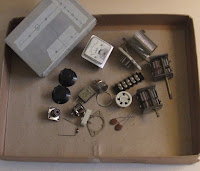
I've found all of the parts and
laid out the chassis. Next step is to drill...I'm committed then.

laid out the chassis. Next step is to drill...I'm committed then.
Subscribe to:
Comments (Atom)


