To see if I'm on the air right now click here

Monday, December 10, 2012

Bruce Kelley Memorial 1929 QSO Party

This past weekend I was able to put a 1929 transmitter on the air and participate in the AWA Bruce Kelley Memorial 1929 QSO Party.

I stayed on 80 meters making 18 contacts. Stations worked were as far west as VE7SL in British Columbia, as for east as N1BUG in Maine and even a little south to N4GJV in North Carolina.


This year I used a transmitter I acquired from Vance, K5CF (SK). Vance, my step father, gave me my novice test in 1966. He enjoyed ham radio for over 70 years. Several years ago Vance encouraged me to participate in the 1929 QSO Party. Vance's transmitter is a TNT (or Tuned plate Not Tuned grid) transmitter using a single type 210 tube. With 340 volts on the plate it runs 9 watts input and about 2 watts out. Vance built his transmitter based on the one Bill Orr described one in the January 1973 issue of CQ but the original design dates from the 20s. See the December 1929 issue of QST for George Grammer's version of the same transmitter. For an antenna I used a 105' end fed inverted L only about 15' off the ground.

Wednesday, December 5, 2012

Bruce Kelley Memorial 1929 QSO Party Preparation

Last night I set up my station for this year's AWA Bruce Kelley Memorial 1929 QSO Party. I decided to go with my TNT transmitter this year and, as a book end for ham technology, pair it with my Elecraft KX3 running as the receiver. With 275 volts on the 210 plates my TNT transmitter runs at just under 10 watts input. Output is 2-3 watts....about to be expected for this sort of transmitter.

After confirming via the Reverse Beacon Network that I was indeed getting out on 80 I tried a QSO this morning. I worked W4DBV near Nashville, TN. When quizzed about my signal Bryan reported:

 "I can't really assign your tone a number, and my verbal description is about as close as I can come.  I have heard much worse, and I have also heard other rigs that are about the same as yours -- usually vintage or HB vintage designs, most running QRP levels of power.  Your note did not have a frank buzz, I can say that."

While not the best signal report it will certainly do for this weekend. In the meantime I'll play with the loading to see if I can improve it a little.

Saturday, August 25, 2012

A Choke Balun for Phased C-Poles


It is important that the baluns used in a phased verticals match, otherwise the phasing, beam pattern and gain won't be as planned. They also must handle the high common mode potential at the feedpoint. KF2YN shows two different balun designs in his April 2004 article. One is just multiple turns of coax wound around a piece of PVC pipe while the second uses a ferrite core. The ferrite core design, while more expensive, also has much less power loss. For my phased verticals I chose Brian's toroid design. It uses 19 turns of RG-174/U coax wound on a FT-240-67 core. I mounted mine in plastic electrical boxes with an eye-bolt to allow hanging from the bottom C-Pole 40" spacer. This balun does no impedance transformation. The balun coax is simply in series with the antenna feedline.


Saturday, August 18, 2012

Phased C-Pole Antennas for some Gain

How many times have we seen 18 wheelers with CB verticals mounted on their mirrors? Doing this, truckers add a little gain on 11 mtrs. With proper spacing this works even better on 20 meters.

Today was a sunny day here in SE MN. The temperature was in the low 70s and there was no sign of rain. It was a great day to meet Rodney, KD0EBT, and Steve, KD0ORM, for a little KX3 time at Rochester's Essex Park. My August 23, 2010 blog post proposing that two C-Poles be fed in phase is based on information in the ARRL Antenna Handbook. Information there states that two verticals fed in phase and spaced 5/8 wavelengths apart exhibit almost 5dB gain over a single vertical. My experiments today seem to confirm this information.

I already have one self supporting 20 mtr C-Pole antenna. I built a second 20 mtr C-Pole. This one hangs from a tree limb like W5USJ 's. A little searching around Essex Pack identified a tree with some open space to the south. I merely hung one C-Pole in that tree and set my self supporting C-Pole about 44' (5/8 wavelength on 14.1 MHz) to the south. This put the two broadside to the east/west. I fed each of the antennas with 50' lengths of LMR-400 low loss coax. At the rig I had a short coax jumper to a tee, connecting my KX3 to both antennas. I let the KX3 internal turner take care of any mismatch caused by driving the two 50 ohm C-Poles in parallel. Measurements using the Reverse Beacon Network showed that these two C-Poles fed in phase and spaced 5/8 wavelength apart really can have 5 dB gain over a single C-Pole.

Now I've another portable antenna option for those days in the park.


Sunday, August 5, 2012

CQs on a Quiet Band and KX3 Trolling Mode

Today it was great weather here in SE Minnesota for getting outside (and it was even a lazy Sunday afternoon!). Beth agreed and she also needed a little time to finish some reading before a Book Club meeting. We packed up a lunch and headed for Bear Creek Park here in Rochester.

Bear Creek Park has restrooms, picnic tables and plenty of tall (but not too tall) shade trees. While not on a hill, it is also not in a hole or valley. It works pretty well for an afternoon QRP outing. In short order Beth and I repositioned a table for shade and antenna.

When I flipped on my KX3 I was not impressed with band conditions. Across 20 mtrs I heard very few signals. I had thought I may try out KX3 / SSB by checking into the Elecraft net on 14303.5 KHz but I didn't bother trying. I moved down to around 14060, the 20 mtr QRP CW frequency, checked the frequency with a few "QRL?"s and then tried a CQ...still no luck. At this point I considered pulling out my own book and calling it a nice day for reading in the park. Chalk one up for solar cycle 24. I'm glad I reconsidered.

The KX3 does have what I call trolling mode. It can be set to send a canned message (such as a CQ), wait a programmable number on seconds, and then repeat the message. During the wait time RIT can be used to tune around for calls. The message buffer can be loaded using paddles but the easiest and most reliable method is to use the KX3 utility provided by Elecraft.

After a few minutes in KX3 trolling mode W5ESE, Scott, in Dripping Springs, TX came back to me. We had a fine QSO discussing the Flight of the Bumblebees QRP contest and central Texas. After wrapping up with Scott a short CQ netted a nice QSO with VE3/W8FIB. Tom was taking a break from fishing and running 3 watts using his K1. According to his grid square location his fishing spot is about 30 miles SW of North Bay, Ontario.

Two nice QSOs and a nice couple of hours in the park ... Don't be afraid to call CQ in a quiet band.

Saturday, July 21, 2012

Back Home

Beth and I just returned from a 5100 mile road trip. My KX3 went along. Even with hot weather and family obligations I managed a few picnic table QRP QSOs.

One of our first stops was Pratt, KS. With 4 hours of free time I asked around for the local park. Lemon Park has lots of trees, shade and tables...prefect for my afternoon. I had nice QSOs with K5KW on 40 and W7LXN on 30

Another stop was Pullman, WA. Here I had an afternoon in Sunnyside Park. I set up next to a walking trail and the frizbee golf course so I had a couple of eyeball QSOs in addition to the ham radio ones. From here I worked KC4ZPB, W9CC and VE3XY, all on 20 CW.

My KX3 running 5 watts CW feeding a 20 mtr endfed zepp continues to be a fun traveling companion.

Monday, June 18, 2012

Update on Another Portable Antenna

I'm pretty happy with my new end fed antenna. Using it Friday evening through yesterday afternoon I've worked NM, PA and OH on 20 and OH and TX on 30. All on CW from my back deck and 5 watt KX3. While not foreign DX, the contacts have been easy to make. Most answered my CQs. Keep in mind also that most of this time band conditions were poor because of a solar flare/storm.

This one is replacing the 58' wire in my KX3 travel bag.

Friday, June 15, 2012

Another Portable Antenna

Tonight I got on the air with my latest endfed wire and had good success working both New Mexico and Pennsylvania.

I've been concerned about running a non-resonant endfed 58' wire with a single counterpoise laying on the ground. It sort of felt like an off center fed windom with half of the antenna on the ground.

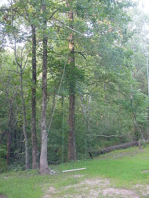
I put together a 20 mtr end fed zepp (14'3" of TV twin lead with the hot side feeding 33'3' of wire) and arranged it as a sloper with the KX3/feedpoint on my deck about 8' off the ground, the twin lead/wire connection about 20' off the ground,  and the far end of the antenna about 1' off the ground. Now the ground side of the antenna system is up in the air rather then laying on the ground. It seems to work pretty good on 20 and as a bonus the KXAT3 antenna tuner can also load it up on 40, 30, 17 and 10. (Not the most efficient radiator on these "bonus" bands but if I can make contacts it is good enough). The reverse beacon system at http://www.reversebeacon.net says I'm getting out.

Besides set up as a sloper (more or less) this antenna can be deployed as an inverted V, an inverted L or a vertical...mostly how ever is convenient to get some part of it up in the air. The 33' 3"portion of mine is Radio Shack insulated 18 gauge stranded copper wire. It runs over tree limbs just fine. Unfortunately Radio Shack no longer sells the light weight twin lead that I used...but any twin lead or ladder line will work but the 14'3"length will need to be adjusted depending on the twin lead velocity factor.

(Just an additional note....where did 33'3" and 14'3" come from?
What I have is a 20mtr EFHW with a quarter wave matching section. At 14.060 MHz a EFHW is 468/14.060 or 33.3'. Even the KX3 ATU can't match this 33'3" wire directly, it is too high of an impedance. The quarter wave matching section transforms the high impedance feedpoint of the EFHW to a lower impedance that the KX3 can handle. At 14.060MHz a quarter wave is 246/14.060 or 17'6". Assuming a velocity factor of 80% gets the length to 14'3". )

(Something else, the  KXAT3/tuner is still needed, even on 20. Nothing's perfect and the twin lead quarter wave matching section can only be said to transform high impedance to low impedance. How high and how low changes with how/where this antenna is deployed. The KXAT3/tuner covers the variable.)

Monday, June 4, 2012

KX3 and a Boat Anchor Amp


A year ago, in a rare foreshadowing of radios to come, I acquired a linear amplifier built around a single 572B running grounded grid. It matched my Central Electronics 20A and the seller
had done really nice job of replacing the four original/modified 1625s in the P&H Electronics LA-400B with a 572B.

Now, seeing it in my shack, I realize that I have a potential May-December wedding here. Sure enough, my KX3 with KXAT3 easily drives the 572B to 100 watts out. The next step is to build a relay box that bypasses the amplifier and delivers -100VDC cutoff bias on receive. It can be controlled via the KX3 Keyline Out signal and a "Keyall" board from Jackson Harbor Press/WB9KZY.

At 35 pounds this one will be a heavy weight. I doubt it will see any picnic table operating but it will certainly help warm up the shack next winter.

Monday, May 14, 2012

New KX3 QSL Card

It's a new "QRP in the Park" season and I have a new rig. I need a new QSL card.

My new card, using Walmart digital photo printing and 3.3"x4" Avery shipping labels, costs about $.30 each in single quantities. This is a great match for my operating style. Rarely do I get on the air and work 100s (or even 10s) of hams in a short time. It would take me forever to work through 100 or more pre-printed QSL cards. This way I can make up QSL cards 5-10 at a time and easily update them without throwing out a bunch of unused cards.

Interested in doing the same? See my January 2, 2010 blog entry.

Sunday, May 13, 2012

KX3 in Silver Lake Park

Today the weather finally turned warm, sunny and dry. It was also Mother's Day, a good reason to avoid the restaurants for a picnic in the park. I did get a chance, though, before the picnic to practice my favorite operating pastime. I found several signals on 20 mtr CW. Gary, K5ON, answered my CQ. We had a great QSO. The KX3 again performed great....love that roofing filter.

Sunday, May 6, 2012

Packing my Elecraft KX3 for a trip

I'm getting ready for summer trips and outings with my Elecraft KX3. I found a the right size padded bag at Goodwill for $3.00. See my video at  KX3PicnicTableQRPPack

Monday, April 16, 2012

Elecraft KX3 is here!


Today I was at the Rochester, MN UPS depot at 10AM sharp to pick up my new radio. I got serial number 43 of, I expect, thousands. Elecraft has crammed a lot into a small box. I spent most of the day figuring out how to use it.

One QSO so far. KB5AE in Ada, OK answered my CQ on 20 CW. He reported a fine 579 signal down his way.

Saturday, February 4, 2012

TZ-20 Amp Output Circuit

This morning I was showing off photos of my TZ-20 amplifier when one of my friends commented that it certainly was wireless, just look at the one rotatory switch with no wires attached to it. This reminded me that I had one last update to post on this project.

After WWII almost every transmitter project (except the simplest starter sets) had a pi network output stage. This was not as common in the 30s. Most transmitters then had link coupled output followed be some sort of antenna matching network. Many times the matching "network" was a variable capacitor either in series or parallel with the output link. A series capacitor worked best for low impedance loads while a parallel capacitor was used to feed into high impedance loads. Today's norm is a 50 ohm antenna antenna/coax system requiring a series capacitor.

SW3, a rotatory switch, controls course loading. C5 is the fine loading adjustment. With SW3 I can switch out the series capacitor all together or add in additional capacitance to give me a total range from about 20pF to 900pF. Tune up becomes very much like a pi network "dip and load". With SW3 and C5 set for minimum capacitance the plate current is dipped using C4. After dipping, the loading capacitance is increased using C5, C6 and C7 into the range of operating plate current and then the current redipped using C4. C4, C5, C6 and C7 interact so this process must be repeated until the last C4 adjustment puts the plate current where it needs to be for full output...in my case about 150 mA. 500 VDC on the TZ-20 plates at 150 mA gives me 75 watts input.

Sunday, January 22, 2012

AWA 2012 Linc Cundall OT CW Contest

This afternoon I wrapped up my participation in this year's Linc Cundall OT CW Contest. Obviously I'm not a major contester. During the 48 hour contest I netted nine contacts. Not many contacts/points but I did enjoy putting my latest homebrew transmitter on the air.

This year I used my new "Taylor 75", a 1934 style oscillator-buffer deck driving two Taylor TZ-20s in push-pull. The receiver was a National NC-101X. Everyone that commented indicated that the transmitter sounded fine. Keying the buffer stage helped. With the crystal oscillator running continuously (on transmit) there was no sign of chirp.

I went ahead and created a QSL card to send out.

Saturday, January 14, 2012

On the Air

Today I got on both 80 and 40 using my new 75 watt transmitter. This afternoon I had a nice QSO on 40 with KC9RXI, Tom, in West Salem, WI and this evening on 80 with NS7E, Art, in New Prague, MN. Both Art and Tom reported no problem with my signal.

Tremendous!

Thursday, January 12, 2012

It Works!

After a couple of days scratching my head and asking around trying to figure out why my TZ-20 amplifier wasn't working up to expectations I finally did what I should have done first. I checked the wiring.

One TZ-20 wasn't connected to the final tank coil. I was running with only half an amplifier and a poorly designed one at that. It worked but not well. Once I fixed the wiring error power levels jumped to the 50-60 watt range. Neat, but now I needed to deal with typical amplifier problems.

TPTG feedback -The first problem I had was that the amplifier took off on it's own (without any drive) when the input/grid circuit was peaked for maximum output. This was solved by removing C3, the TZ-20 grid tuning capacitor, from the circuit. C3 in the amplifier and C8 in the final tank circuit of my 1934 transmitter interacted anyway so this eliminated one pesky control. Problem solved but now the drive level was way down...one solution led to another problem.

Drive level - With no tuned circuit on the grids of my TZ-20s they were not getting the drive needed to get anywhere close to full output. This one was solved with a new coil for L1/L2. More turns for L2 got the power transfer up to the point that now I'm easily driving the amplifier to 75 watts input.

Bias - This all started with me wondering if I has the bias set right. The advantage of the TZ-20s is that they do not need an external bias supply to protect them when the drive goes away. With no drive (and no bias) plate current drops to almost zero. For the TZ-20 a simple resistor from the grid to ground is all that's needed to produce needed bias....but what value? It turns out that the 1939 Taylor tube manual has a formula for calculating recommended Class C CW grid bias for a given plate voltage, in my case 500V. Bias came out approximately 20 volts. I'm driving the grids to about 30mA ... 20V/30mA = 666 ohms. I had a 750 ohm resistor, close enough.

One question that had to be dealt with was how best to couple the output to the antenna. It turns out that, for my 40 turn tank coil, a four turn link gives me maximum output into my 50 ohm dummy load. I am set up, though, so that I can add a loading capacitor in series with the link to cover real world antenna conditions.

Now I have an amplifier for my 1934 transmitter that takes about 6 watts of drive to run 75 watts input (45-50 watts output) on 80. With a couple of new coils I should be able to put it on 40.

Look for me during the AWA Linc Cundall OT CW contest next week.

Saturday, January 7, 2012

TZ-20 Operating Specs?


I've gotten my TZ-20 RF amp up and running with my three tube 1934 transmitter but its not working like I expected.

I'm running with 500V on the push-pull plates with the recommended 2K bias resistor. Key down I'm seeing grid current (total for the two tubes) of about 40mA and total plate current of 40-50mA. Looking at the TZ-20 specs and tubes curves from the 1939 Taylor Tube manual I expected to see 50-75 watts input with 35-50 watts output, instead I'm seeing 20-25 watts input and only 8-10 watts output. I do have three TZ-20s. Any two of them behave the same. What an I doing wrong...or is it working as designed?