To see if I'm on the air right now click here

Saturday, December 18, 2010

2010 AWA Bruce Kelley QSO Party

The last two weekends I participated in the AWA Bruce Kelley QSO. Except for curious visitors, transmitters must be limited to 1929 (or earlier) designs and not crystal controlled.

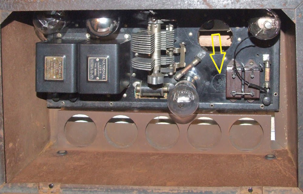
This year I used my Hull Hartley at 10 watts input and a Drake 2B receiver. The change from last year was having a 80 mtr vertical available rather than a simple end fed wire. Unfortunately SE MN was under a blizzard warning for most of the first weekend of the party and I was busy elsewhere for most of the second weekend. Self excited oscillators like the Hull Hartley are prone to frequency wobble whenever the antenna load changes. My vertical swaying in the blizzard wind was too much for it. Rather than wobble all over the band I again used my 105' end fed inverted "L".

Even with only 3 watts out to a low (10' -15' off the ground) antenna I made 11 contacts and worked both east and west coasts. I had a good time.

Maybe next year I'll have an amplifier for my Hartley so that I can use the vertical (with the sway) and run closer to 6-7 watts out.

Thursday, December 9, 2010

80 Mtr Vertical Performance


I wondered if my 80 mtr top loaded vertical is a good antenna for the Bruce Kelley Memorial 1929 CW QSO Party. Part of the loading is the top 6' of two of the guys. Any sway at all causes a guy to sag a little shifting the load my Hartley sees. This causes my signal to FM/wobble...distracting to say to least and aggravating if the band is crowded. I needed to know if the gain offered by the vertical over my endfed wire was enough to outweigh the the wobble it introduced.

The reverse beacon network at http://www.reversebeacon.net/ allowed me to get a good idea of real antenna performance. All I had to do is call CQ and any reverse beacon stations hearing me automatically posts my call, frequency and signal strength to the web. By switching between my low endfed wire and my vertical I could get a good A vs B comparison. By doing this over a period of time I could see how changing nighttime propagation impacts this comparison. Monday night I did exactly this and then sorted though the data to see how the two antennas compare from about 8PM (2:00 UTC) through the next morning.

What I found was that for the east coast (PA) the vertical offered 8-10 dB gain throughout the night. While not always a spectacular performer it is almost always better than my endfed wire...but signal reports all mention the wobble/FMing introduced by antenna sway. Based on this I'll stick with my endfed wire for the early evening hours and then switch after about 10PM when the band activity dies down a little.

For next year's Bruce Kelley QSO Party it would be nice to have this problem solved by building a '29 style amplifier to use with my Hartley. Fortunately my 1934 transmitter already has an amplifier stage in between the oscillator and the antenna. My vertical will work fine with this transmitter during the AWA Linc Cundall Memorial CW Contest in January.

Saturday, November 6, 2010

More 80 Meter Vertical

Yesterday I did the final pruning on my 80/40 meter vertical.

This antenna is a big improvement over my 105' endfed wire. Last night on 80 CW running only about 10 watts I worked KK1K (VT), VE7SL (BC) and VE3AWA (ONT). All gave me good signal reports and had no trouble with the QSOs. In addition VE7SL reported I went from s6-s7 to unreadable when switching back to the endfed wire. VE3AWA reported that I went from s9 plus to s8 when switching to the endfed wire.

I also checked my antenna performance used the Reverse Beacon Network at http://www.reversebeacon.net .This is a network of receivers/computers connected to the internet. They auto log the frequency and signal level of any CQs heard. By calling CQ using both the vertical and the endfed wire I got a good idea on how the two antennas compare. The network consistently logged me when I used the vertical and never heard me when I used the endfed wire. At the locations on the Reverse Beacon Network, the vertical was the clear winner. But there were no reverse beacon stations in MN, WI or IA. My endfed wire might have done better if evaluated using nearby reverse beacon stations locations.

I was asked about my radial system. I have eight 30' insulated wire radials stapled in the grass. 30' seems short, I expected to need 67' (1/4 wave on 80) long radials. I measured the resonant frequency of the radial system as I would an 8 element fan dipole with two 4 element halves. 30' seemed to be right. Velocity factor must have a big impact on the length of ground mounted radials.

This new vertical should definitely help my AWA QSO Party scores.

Monday, October 11, 2010

More 80 Meter Vertical

Beth has commented that I need to get a "Frequent Buyer" card for my local big box hardware store. Since starting on this project I've been making trip after trip to buy yet one more bunch of screws, a particular clamp, a spool of wire, a ..... the list goes on. For a project that started with a $7 set of fiberglass poles this one certainly is a great example of "the devil's in the details".

I'm finally to the point of pruning it to frequency. Along the way I've fashioned a hinged base out of a large gate hinge and two conduit hangers, I've added 40 meter capability and I've made the bottom 23' a four wire vertical cage. Top loading is provided by two 6' elements forming the top ends of two of the guys, a coil wound out of 14 gauge insulated wire on a piece of 4" thin wall PVC sewer pile and a vertical 6' element. 40 meter coverage is provided by a 9' stub (connected directly to the top of the 23' vertical cage below the coil) that makes up the top of the third guy. Additional support is provided by tying the mast to my deck railing at approximately the 9' level.

Normally this will be a winter installation. I plan to paint the mast white.

Actual on the air reports will need to wait until I finish tuning it to 3560KHz.

Wednesday, September 1, 2010

80 meter vertical

As I look forward to cooler weather I've starting to think about 80 meters. With the winter months 80 becomes quieter and a better band for "DX". 80 is also to best band for my 1929 transmitters. I'd like to put up a better 80 meter antenna. Right now my endfed wire is only 10'-15' off the ground. If works OK for Minnesota but not much else beyond that. The radiation angle is too high. My backyard was too recently a corn field. Nothing back there is tall enough to support a higher dipole or end fed wire.

I'm going to start with a 30' to 35' 80 meter center loaded vertical and maybe even top load it a little. For a mast I'm going to try some of the fiberglass camouflage netting support poles / antenna masts seen on ebay these days. AI4WM has a good article on the web describing these poles . I found some with the fiberglass reinforcing ring on ebay fairly cheap. A trip to my local big box hardware store resulted in several "attachments pictured:


  1. 1.5" Conduit Hanger - This allows me to attach coils, pulleys, etc to a mast or they can be used to attach to mast to something else (like a fence or a post).


  2. 1.25" PVC Cross - This fits nicely over the top/male end of the mast.


  3. 2" x 1.5" PVC Reducer - This I found in the electrical department. With a little drilling to add a few wire loops I should be able to use this to attach guys


  4. 1.25" PVC Plug - This goes in the top (when mounted) arm of the PVC cross. It will give me a place to add a 6' whip above the top fiberglass mast.


Monday, August 23, 2010

More C-Pole Vertical Array

After building/using my two C-Pole array I'm starting to rethink my plan.

KF2YN's C-Pole vertical array design calls for dedicated C-Poles (each pruned to have a 25 ohm input impedance) and phasing lines that both transform the antenna impedance to 100 ohms and set the phase delay between the two antennas. On the surface this looks doable but I've a lot of concern about getting the phasing lines right. W8WWV's measurements showed about a 4% delta as he measured the electrical length of a 17.1' long piece of coax. Also, I don't want to dedicate two C-Poles to an antenna that I won't be using much.

A local friend of mine wants to build a self supporting C-Pole antenna like mine. I can feed two verticals with arbitrary (but equal) lengths of coax and a simple Tee connector at the antenna tuner to make up for the 25 ohm combined feed impedance...no need to worry about electrical lengths. In addition, self supporting antennas can be positioned anywhere to point my signal where I want it to go that day. I can even boost the gain a little (up to 4.8 dB) by separating the antennas 5/8 wavelength.

It's still August, I should have another couple of months of outside weather here in Minnesota.

Wednesday, August 11, 2010

A Two C-Pole Steerable Array


Yesterday I finally got my two C-Pole phased array up and on the air. In fact, after tuning it a little I easily made two QRP contacts, one with N2UGB in NY and the other with CT4RL/1 in Portugal.

My journey from idea to an antenna was based on Chapter 13.3, "A Steerable C-Pole Array" in Brian Cake's book, "Antenna Designer's Notebook". Here Brian presented a design based on phased array theory and modeling. Brian was not aware of anyone that had actually built one.

The C-Poles themselves are made from Radio Shack 18 gauge stranded hookup wire. 1/2" PVC pipe is used for the top and bottom 40" spreaders. For easy supporting, the two C-Poles are in the same plane and aligned with the rope joining the two antennas. The upper inside corners of the antennas are connected by a 33.5' length of rope. This insures correct spacing. Support ropes are tied to the two top outside corners. Instead of a relay I used a coax T connector. L3 was added/removed as needed to change the radiation pattern.

Without L3 the array is endfire and, according to Brian's modeling, good for 1.18dBi gain. By adding L3 into the short/L2 side both sides become 3/4 wavelength long and the array has 3.5 dBi gain broadside.

I learned a little along the way about...
  • Baluns and phasing lines...The phasing lengths include the phase delay introduced by the required choke baluns. I had planned to use air core baluns consisting of RG-8X wound around 4" plastic coffee "cans". What I found was that each balun takes about 1/4 wavelength (electrically) of coax. By the time I added the baluns to L1 and L2 in the accompanying diagram I couldn't separate the antenna by a physical half wave. I was forced to use more expensive ferrite toroid baluns that require less coax.
  • Adding/removing L3...The switch/relay proposed by Brian in his design introduced its own challenges. The relay/switch is part of the phasing network. I found that my DPDT toggle switch with the needed connectors introduced more phase delay to the point that I was again in trouble with the physical separation of the two antennas. I eventually used a T connector instead.
  • Supports...Finding trees with the right separation, orientation, height and limb placement can be a problem...especially for a temporary installation in the park.
  • Measuring the electrical length of coax...My MFJ Antenna Analyzer gave a broad X=0 reading. My grip dip meter gave a sharp dip but not on the same frequency as the MFJ (The ARRL Antenna Book recommends against using a dip meter). Eventually I averaged the two MFJ endpoint/X=0 readings to get a center/single frequency and then calculated the coax electrical length based on that frequency.
  • Gain...1 to 3.5 dBi of gain is hard to notice when asking for signal strength comparisons under real band conditions.
This antenna array may be a good alternative for someone with properly located supports but my typical picnic table operating style doesn't always allow that. This was as interesting exercise but I'll probably keep using my single C-Pole when I'm at the park.

Tuesday, July 27, 2010

QRP operating at Myre-Big Lake State Park


This last weekend Beth and I took our camper trailer to Myre-Big Lake State Park near Albert Lea, MN. I had along my K1 and Crappie Pole 20 mtr C-Pole vertical.

As expected the C-Pole antenna worked well. Over the weekend I had 11 contacts including WA3SLN (PA), K4SPO (KY), K3WWP (PA), AF4O (TN), WB2PEF (NY), VA3RKM (ONT), WB6OJB (CA),WB4KLI (KY), WD9F (IL), W2IQK (NY) and W9LD (WA). I also started a QSO with AB7KT (NV) but that QSO was as victim of QSB/QRM/QRN.

Charles, K1ETU, from Oneonta, NY, spotted me and stopped by for an enjoyable "eyeball QSO". Bill, a camper from Louisville, KY, also stopped by bringing his two sons. Bill has been interested in ham radio since a teenager but had never gotten a license. Now he's thinking of locating a Louisville Radio Club and working on getting his ticket.

The crappie pole frame for my C-Pole really stands out in a campground. It looks like some sort of tall skinny game target or goal. Lots of campers noticed it as they walked or drove by, some asked about it. My favorite comment: "I've never seen a camping accessory like that before".

Thursday, June 24, 2010

More W0VLZ Operating

Strong signals are few and far between here at the Shady Creek Resort but I'm still been able to make contacts using my K1 running five watts into my Crappie Pole C-Pole antenna.

My surprise contact yesterday was EA6UN on the Balearic Islands off the coast of Spain in the western Mediterranean Sea. That's over 4600 miles on my five watts. I found Jurek calling CQ on 14.050 MHz with no responses. He came right back to me and gave a 579 report. Today's QSOs have all been to the west...WB6HGJ (CA), W7LPV (AZ) and N6IV (CA).

Tuesday, June 22, 2010

W0VLZ Operating

I have almost a week to kick back at a lake resort here in north central Minnesota. As usual I have my K1 along. In the past I would have made use of a tree as an antenna support for my end fed 67' wire antenna. This time I'm using my Crappie Pole C-Pole antenna.

Conditions have been marginal at best with strong signals few and far between and QSB the order of the day. Daily operating has been rewarded by a few contacts....VE3FIT (Toronto, ON), N3EIN (Coatesville, PA) and
W9FHA (Evansville, IN). Another contact, with K9WWT in Merrillville, IN, was a victim of QSB. My signal went from 589 to unreadable in the length of George's initial transmission.

Thursday, June 10, 2010

The Mitey Mite Beginner Transceiver

Last weekend I attended the TwinsLAN/3M swapmeet in St Paul, MN. This is always one of my favorite swapmeets of the year. It is open-air in a large parking lot so all of the boatanchors show up that we don't want to lug inside to a table...just throw open the van doors or uncover the pickup bed and sell.This year I saw many more boat Nationals, Hallicrafters, Johnsons and Heathkits than I've seen in the past...it was a great meet.

One item caught my attention, a late 40's United Surplus Materials "Mity Mite" HF radio. It is a three tube regenerative receiver/transmitter. The audio stage of the two tube receiver doubles as a single tube crystal controlled oscillator/transmitter. The third tube is a rectifier. I bought it from KB0DVM. He built and used this little rig while he was an Ag student at U of Wisconsin/Madison in 1948.

This is a great example of a minimal design making use of available WWII surplus parts. The first steps in the instruction manual explain how the disassemble the included BC-745 pogo stick transceiver tuning unit to get the crystal, two sockets, a tuning coil and the bandset capacitor. The design itself would not make it off of today's drawing boards. First it is an AC-DC set with one side of the AC line connected directly to the metal chassis/cabinet...what a shocker! A safer (and more expensive) AC-DC design has circuit ground isolated from the chassis but not this one. A quick look at the operating instructions shows a note about not connecting an antenna ground but nothing about the shock hazard. Next there is no tuned circuit in the transmitter output. Any harmonics generated by the crystal oscillator are passed unattenuated to the antenna. Again not a good design but it works, though on several bands at the same time.

The Mity Mite is a pretty neat little radio that reflects the time and market it was designed for. It is a keeper. I'll probably figure out a way to put it on the air (while staying on one band and not killing myself).

Monday, May 31, 2010

A C-Pole Antenna for QRPxpeditions

I've finished yet one more version of my Crappie Pole antenna, this one based on KF2YN's ground independent vertical antenna (or C-Pole). See here and April 2004 QST, page 37, for more information. After trimming it a little it measures 1:1 at 14.060 MHz rising to 2.5:1 at 14.35MHz and 1.2:1 at 14.0MHz.

I found the choke balun to be key to making this antenna work. With no choke the SWR was over 14:1 at 14.060MHz and with a 10 ferrite bead choke the SWR was still 2.8:1 at 14.060MHz. What I'm using now is 15 turns of RG8X single layer wound on a 4" plastic coffee can.

This antenna is about 18' tall, self supporting without guys and has only a 4' x 5' footprint. It breaks down to a bundle 5' long. Physically it looks like a tall skinny goal post. Add a birdie and two racquets and it should fit well into a typical camping weekend.

View a video of me setting up this antenna at

https://youtu.be/nYn-GnwcSoE

Today I made several nice contacts using my K1 at 5 watts and this antenna including W8CQU in Ohio (599), WA3SLN in Pennsylvania (449), W0WCA in Colorado (449), KI0II in Colorado (549) and N4ESS in Florida (579).

This antenna is going with us when we go camping this summer. Thank you KF2YN.

Update: On June 23 I worked EA6UN on the Balearic Islands off the coast of Spain in the western Mediterranean Sea. That's over 4600 miles on my five watts and this antenna. I found Jurek calling CQ on 14.050 MHz with no responses. He came right back to me and gave a 579 report.

Monday, May 24, 2010

An SW-4 Mystery

A friend of mine noticed that my National SW-4 shown at http://www.prismnet.com/~nielw/nat_list/sw4.htm uses what looks like standard SW3 type audios as opposed to the National "Duo Coupler" mentioned in the SW-4 ad. Other National radios show a production process that used parts that were available. Close inspection and comparisons between National receivers of the same model can show undocumented differences in details. Are this audios replacement parts or do they reflect a production change to take advantage of existing stock?

As I looked at these audios I saw something else. Close inspection of my SW-4 bakelite chassis showed three large plugged holes and several plugged small bolt holes. Parts mounting and the quality of the work makes it appear that all of this chassis rework was done before most of the parts were mounted. Why all of the extra plugged holes? Was the chassis originally drilled for another product and then reworked? Was the chassis made from a piece of bakelite that already had a few holes in it? Did a worker make several errors that had to be fixed before the chassis could be used?

There are a few SW-4s still around. I wonder, do they show similar changes and reworks? Were these sorts of production techniques common or is this really a set that was carefully reworked at some point after it left the factory?

Monday, May 17, 2010

A 20 Meter Crappie Pole Vertical


This past weekend we had nice weather here in southern Minnesota....mostly sunny and temperatures around 70. I spent some time working on a new portable antenna and then using it on the air.

I was looking for something simpler than my 20 Meter Crappie Pole Vee dipole. I decided to try a quarter wavelength vertical. The March 2010 issue of QST has a good article on ground systems for vertical HF antennas. Based on that I concluded that a 1/4 wave length vertical with only 4 elevated resonant radials should perform fairly well. What I ended up with is a 16 1/2' crappie pole on top of a 4' base section. The crappie pole itself is non-conductive fiberglass. It serves only as a support for the vertical wire. The guys at the top of the base section are 14 gauge stranded copper wire. These are trimmed to resonate on 14.05 MHz and serve as antenna radials sloping from 4' at the base of the vertical to about 1' were they are each tied off with adjustable lines.

On Saturday while using this antenna and my K1 I worked WA0FJT in Independence, MO on 14.050. There was some QSB but our 5 watt CW signals were usually 589 both ways. I got on the air again on Sunday afternoon and worked WB4YXD (New Mexico), N4HUS (Arizona), W2LG (Florida) and KB2DHG (New York). All came back to my CQs on a fairly quiet/vacant band. Via email I even received a reception report from W1CTT (Maine).

The antenna seems to be fairly effective but the elevated 16' radials could be a problem, especially in a full campground or picnic area. I'll look some more for a 20 meter self supporting antenna that fits better into an average campsite

Sunday, May 2, 2010

Monday, April 19, 2010

More TZ-20 Amplifier


With the chassis and front panel drilled, punched and painted this project should start looking more like a kit. Everything is in hand, all I need to do is mount, wire and solder.

I laid out the chassis and front panel so that eventually this amplifier will serve as an upper deck of a 70 watt CW transmitter. My 1934 transmitter will be the lower deck/driver.

Tuesday, April 13, 2010

Springtime - QRPtime

With an early spring here in SE Minnesota I can start thinking about QRP again. One of my favorite local picnic table QRP spots here in Rochester is Essex Park. It has plenty of space, lots of trees with limbs about right for antenna supports and movable picnic tables. Take a look here for a video on my operating from Essex park. On Saturday I worked N1LU, Don in NH, and K1TG, Roger in CT. K1TG was an especially good QSO. We are both active in the AWA and have worked each other using our vintage stations.

This weekend at Essex Park I also worked on a new antenna. My end fed half wave and full wave wire antennas do a fine job but they require at least one well placed tree. I could use a self supporting antenna. Cabellas (and other big box sporting goods stores) sell a 16.5' collapsible crappie (as in fishing) pole. 16.5' is just about right for half of a 20 meter dipole. On Sunday I setup two of these poles to form a V to support a V (not inverted V) dipole. Read more about this antenna here. It appears to work as well as a straight dipole and it is fairly portable....now I need to find a bare nob of a hill to operate from.

Saturday, March 27, 2010

National TRM 56 MC Transceiver


Last week I acquired a 30's vintage National 56 MC transceiver. Read about this model on my web site at http://www.prismnet.com/~nielw/TRM_TRW/TRMpage.htm . The TRM and the wooden cased TRW were two of the first commercially available VHF radios. At only 6"x6"x7.5" and 8.5 pounds it is amazingly heavy for it's size. The two special National transformers add a lot to the weight.

I don't find much information about the TRM. What I've found is from National's 1935 catalog and a 1933 article that, while it doesn't mention it by name, appears to describe the TRM. None of my catalogs mention the TRM or TRW after 1935 but my TRM has a model tag. National didn't but tags on their equipment until after James Millen left in 1938. This one must be a late model.

Thursday, March 18, 2010

Another Swapmeet Find


Here's something that I keep around to show visitors that hams really did build the transmitters described in QST. Take a look at my version of George Grammer's push-pull TNT transmitter. This one here is a lot worse for wear but it is recognizable.

Wednesday, March 10, 2010

Swapmeet Find

Every once and a while over the years I've picked an item at a swapmeet just because it was interesting and if it could talk would have a story to share.

Here's one. I don't remember when or where I got it but probably at a central Texas swapmeet a few years ago. Some one on a budget wanted to get into ham radio. The local trash heap contributed an old crystal set complete with loose coupler. The tuning coil was rewound as the antenna transformer primary. Some tuning was allowed by striping off insulation in a few places. The loose coupler became the antenna coil and allowed variable coupling. I found a section of the Sunday comics shoved into the loose coupler to keep it in place..date1930. Two of the holes on the board next to the spark coil match the mounting holes for a Bunnell telegraph key.

Friday, March 5, 2010

More RF Amp


A push-pull amplifier is two tuning caps, two coils and two tubes right? With all of the support circuitry, the output loading circuit I like and miscellaneous parts and hardware it is starting to look like a real project. Once the drilling is done this one will sit until warm weather returns to Minnesota (maybe May?). I want to paint the chassis but not with snow on the ground and temperatures in the 30s.

Sunday, February 21, 2010

RF Amp


Most of my 30s vintage transmitters are in the 10-20 watt range. It would be fun to have a little more power, especially with my 10 watt Meissner Signal Shifter / VFO. According to the specs two Taylor TZ20s in push-pull can be driven with 5 watts to about 110 watts input or 85 watt output. This sounds like what I'm looking for.

As usual any project starts with sorting through parts and then doing a preliminary layout before taking a drill to the metal.

Friday, February 5, 2010

1929 and 1930 Stations

Lots of times questions get asked about what sort of rig to put on the air as a 1929 station. What were hams really using? Do the back page ads in QST really reflect what was on the air?

As I went through my old issues of the AWA OTB/Journal I found Bruce Kelley's comments on 1929 equipment in the May 1994 issue. He summarized 1929 and 1930 QSL card information from W1NE. He saw that Hartley oscillators and the 210 dominated the transmitter scene and almost 90% of the receivers had no RF stage. I found two 1930 QSL cards in my collection and added those to Bruce's tabulation. I've posted this data at http://www.prismnet.com/~nielw/OldQSLCardInfo2.pdf .

If you have similar 1929 or 1930 QSL data email it to me and I'll add it to the summary.

Monday, January 25, 2010

AWA Linc Cundall Memorial OT CW Contest


For two days this past week I participated in the AWA Linc Cundall Memorial OT CW Contest. This contest gives a significant multiplier to those using pre 1947 gear. I used a National NC-101X and one of my recent homebrew transmitters, a "46 job". I worked nine stations in four states plus Ontario.

Saturday, January 2, 2010

Photo QSL Cards


QSL cards are a ham radio tradition that I was introduced to when I was a novice in 1966. My novice card then was a fairly generic design ordered 100 cards at a time from the Little Print Shop near Austin, Texas.

These days I usually custom create my QSL cards to go with a particular event or location. Lots of places will print digital photos and most allow on-line submission. I've seen prices as low as 9 cents per print with no minimum. All that is needed is a jpg file the right size.

Start with your favorite graphics editor, even Microsoft Paint has enough power and function to do the job.

First create a blank colored background with the right aspect ratio to match the prints to be ordered. I planned to order 4" x 6" prints so I created a 800 x 1200 pixel background. This background gives you control over auto resize/crop that occurs when your file is printed. The color doesn't matter. It will eventually get trimmed off.

Use your editor to cut out from the middle of the background a rectangle the matches the final size of the QSL card. For a typical 3.5" x 5.25" QSL card on a 800 x 1200 pixel background this rectangle will be 700 x 1050 pixels. This space is where you create your QSL card.

Use your graphics editor to add whatever QSL card text and images you wish. For Microsoft Paint I found it best to crop and resize any photos or images before I paste them into the QSL card.

Send the jpg file off to be printed.

The resulting 4" x 6" print will have a colored frame that needs to be trimmed off. This should leave your 3.5" x 5.5" QSL card. A paper cutter works great for trimming.

Other cheaper options may be available but for the QSL card information I use a Avery #5264 3.25" x 4" shipping label stuck to the back of the QSL card. Inside the Avery box are instructions telling how to use a template included in Microsoft Word to create six preprinted labels per sheet of shipping labels.