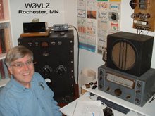
 when one of my friends commented that it certainly was wireless, just look at the one rotatory switch with no wires attached to it. This reminded me that I had one last update to post on this project.
After WWII almost every transmitter project (except the simplest starter sets) had a pi network output stage. This was not as common in the 30s. Most transmitters then had link coupled output followed be some sort of antenna matching network. Many times the matching "network" was a variable capacitor either in series or parallel with the output link. A series capacitor worked best for low impedance loads while a parallel capacitor was used to feed into high impedance loads. Today's norm is a 50 ohm antenna antenna/coax system requiring a series capacitor.
SW3, a rotatory switch, controls course loading. C5 is the fine
 loading adjustment. With SW3 I can switch out the series capacitor all together or add in additional capacitance to give me a total range from about 20pF to 900pF. Tune up becomes very much like a pi network "dip and load". With SW3 and C5 set for minimum capacitance the plate current is dipped using C4. After dipping, the loading capacitance is increased using C5, C6 and C7 into the range of operating plate current and then the current redipped using C4. C4, C5, C6 and C7 interact so this process must be repeated until the last C4 adjustment puts the plate current where it needs to be for full output...in my case about 150 mA. 500 VDC on the TZ-20 plates at 150 mA gives me 75 watts input.
