Strong signals are few and far between here at the Shady Creek Resort but I'm still been able to make contacts using my K1 running five watts into my Crappie Pole C-Pole antenna.
My surprise contact yesterday was EA6UN on the Balearic Islands off the coast of Spain in the western Mediterranean Sea. That's over 4600 miles on my five watts. I found Jurek calling CQ on 14.050 MHz with no responses. He came right back to me and gave a 579 report. Today's QSOs have all been to the west...WB6HGJ (CA), W7LPV (AZ) and N6IV (CA).
Thursday, June 24, 2010

Tuesday, June 22, 2010
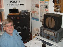
W0VLZ Operating
I have almost a week to kick back at a lake resort here in north central Minnesota. As usual I have my K1 along. In the past I would have made use of a tree as an antenna support for my end fed 67' wire antenna. This time I'm using my  Crappie Pole C-Pole antenna.
Conditions have been marginal at best with strong signals few and far between and QSB the order of the day. Daily operating has been rewarded by a few contacts....VE3FIT (Toronto, ON), N3EIN (Coatesville, PA) and
W9FHA (Evansville, IN). Another contact, with K9WWT in Merrillville, IN, was a victim of QSB. My signal went from 589 to unreadable in the length of George's initial transmission.
 Crappie Pole C-Pole antenna.
Conditions have been marginal at best with strong signals few and far between and QSB the order of the day. Daily operating has been rewarded by a few contacts....VE3FIT (Toronto, ON), N3EIN (Coatesville, PA) and
W9FHA (Evansville, IN). Another contact, with K9WWT in Merrillville, IN, was a victim of QSB. My signal went from 589 to unreadable in the length of George's initial transmission.
Thursday, June 10, 2010
The Mitey Mite Beginner Transceiver
Last weekend I attended the TwinsLAN/3M swapmeet in St Paul, MN. This is always one of my favorite swapmeets of the year. It is open-air in a large parking lot so all of the boatanchors show up that we don't want to lug inside to a table...just throw open the van doors or uncover the pickup bed and sell.This year I saw many more boat Nationals, Hallicrafters, Johnsons and Heathkits than I've seen in the past...it was a great meet.
One item caught my attention, a late 40's United Surplus Materials "Mity Mite" HF radio. It is a three tube regenerative receiver/transmitter. The audio stage of the two tube receiver doubles as a single tube crystal controlled oscillator/transmitter. The third tube is a rectifier. I bought it from KB0DVM. He built and used this little rig while he was an Ag student at U of Wisconsin/Madison in 1948.
This is a great example of a minimal design making use of available WWII surplus parts. The first steps in the instruction manual explain how the disassemble the included BC-745 pogo stick transceiver tuning unit to get the crystal, two sockets, a tuning coil and the bandset capacitor. The design itself would not make it off of today's drawing boards. First it is an AC-DC set with one side of the AC line connected directly to the metal chassis/cabinet...what a shocker! A safer (and more expensive) AC-DC design has circuit ground isolated from the chassis but not this one. A quick look at the operating instructions shows a note about not connecting an antenna ground but nothing about the shock hazard. Next there is no tuned circuit in the transmitter output. Any harmonics generated by the crystal oscillator are passed unattenuated to the antenna. Again not a good design but it works, though on several bands at the same time.
The Mity Mite is a pretty neat little radio that reflects the time and market it was designed for. It is a keeper. I'll probably figure out a way to put it on the air (while staying on one band and not killing myself).
 up that we don't want to lug inside to a table...just throw open the van doors or uncover the pickup bed and sell.This year I saw many more boat Nationals, Hallicrafters, Johnsons and Heathkits than I've seen in the past...it was a great meet.
One item caught
 my attention, a late 40's United Surplus Materials "Mity Mite" HF radio. It is a three tube regenerative receiver/transmitter. The audio stage of the two tube receiver doubles as a single tube crystal controlled oscillator/transmitter. The third tube is a rectifier. I bought it from KB0DVM. He built and used this little rig while he was an Ag student at U of Wisconsin/Madison in 1948.
This is a great example of a minimal design making use of available WWII surplus parts. The first steps in the instruction manual explain how the disassemble the included BC-745 pogo stick transceiver tuning unit to get the crystal, two sockets, a tuning coil and the bandset capacitor. The design itself would not make it off of today's drawing boards. First it is an AC-DC set with one side of the AC line connected directly to the metal chassis/cabinet...what a shocker! A safer (and more expensive) AC-DC design has circuit ground isolated from the chassis but not this one. A quick look at the operating instructions shows a note about not connecting an antenna ground but nothing about the shock hazard. Next there is no tuned circuit in the transmitter output. Any harmonics generated by the crystal oscillator are passed unattenuated to the antenna. Again not a good design but it works, though on several bands at the same time.
The Mity Mite is a pretty neat little radio that reflects the time and market it was designed for. It is a keeper. I'll probably figure out a way to put it on the air (while staying on one band and not killing myself).
Monday, May 31, 2010
A C-Pole Antenna for QRPxpeditions
I've finished yet one more version of my Crappie Pole antenna, this one based on KF2YN's ground  independent vertical antenna (or C-Pole). See here and April 2004 QST, page 37, for more information. After trimming it a little it measures 1:1 at 14.060 MHz rising to 2.5:1 at 14.35MHz and 1.2:1 at 14.0MHz.
I found the choke balun to be key to making this antenna work. With no choke the SWR was over 14:1 at 14.060MHz and with a 10 ferrite bead choke the SWR was still 2.8:1 at 14.060MHz. What I'm using now is 15 turns of RG8X single layer wound on a 4" plastic coffee can.
This antenna is about 18' tall, self supporting without guys and has only a 4' x 5' footprint. It breaks down to a bundle 5' long. Physically it looks like a tall skinny goal post. Add a birdie and two racquets and it should fit well into a typical camping weekend.
View a video of me setting up this antenna at
https://youtu.be/nYn-GnwcSoE
Today I made several nice contacts using my K1 at 5 watts a nd this antenna including W8CQU in Ohio (599), WA3SLN in Pennsylvania (449), W0WCA in Colorado (449), KI0II in Colorado (549) and N4ESS in Florida (579).
This antenna is going with us when we go camping this summer. Thank you KF2YN.
Update: On June 23 I worked EA6UN on the Balearic Islands off the coast of Spain in the western Mediterranean Sea. That's over 4600 miles on my five watts and this antenna. I found Jurek calling CQ on 14.050 MHz with no responses. He came right back to me and gave a 579 report.
 independent vertical antenna (or C-Pole). See here and April 2004 QST, page 37, for more information. After trimming it a little it measures 1:1 at 14.060 MHz rising to 2.5:1 at 14.35MHz and 1.2:1 at 14.0MHz.
I found the choke balun to be key to making this antenna work. With no choke the SWR was over 14:1 at 14.060MHz and with a 10 ferrite bead choke the SWR was still 2.8:1 at 14.060MHz. What I'm using now is 15 turns of RG8X single
 layer wound on a 4" plastic coffee can.
This antenna is about 18' tall, self supporting without guys and has only a 4' x 5' footprint. It breaks down to a bundle 5' long. Physically it looks like a tall skinny goal post. Add a birdie and two racquets and it should fit well into a typical camping weekend.
View a video of me setting up this antenna at
https://youtu.be/nYn-GnwcSoE
Today I made several nice contacts using my K1 at 5 watts a
 nd this antenna including W8CQU in Ohio (599), WA3SLN in Pennsylvania (449), W0WCA in Colorado (449), KI0II in Colorado (549) and N4ESS in Florida (579).
This antenna is going with us when we go camping this summer. Thank you KF2YN.
Update: On June 23 I worked EA6UN on the Balearic Islands off the coast of Spain in the western Mediterranean Sea. That's over 4600 miles on my five watts and this antenna. I found Jurek calling CQ on 14.050 MHz with no responses. He came right back to me and gave a 579 report.
Monday, May 24, 2010
An SW-4 Mystery
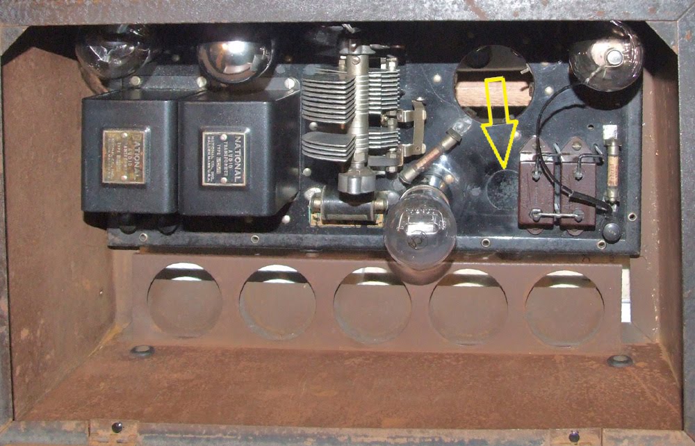
A friend of mine noticed that my National SW-4 shown  at http://www.prismnet.com/~nielw/nat_list/sw4.htm uses what looks like standard SW3 type audios as opposed to the National "Duo Cou
 pler"
pler"  mentioned in the SW-4 ad. Other National radios show a production process that used parts that were available. Close inspection and comparisons between National receivers of the same model can show undocumented differences in details. Are this audios replacement parts or do they reflect a production change to take advantage of existing stock?
As I looked at these audios I saw something else. Close inspection of my SW-4 bakelite chassis showed three large plugged holes and several plugged small bolt holes. Parts mounting and the quality of the work makes it appear that all of this chassis rework was done before most of the parts were mounted. Why all of the extra plugged holes? Was the chassis originally drilled for another product and then reworked? Was the chassis made from a piece of bakelite that already had a few holes in it? Did a worker make several errors that had to be fixed before the chassis could be used?
There are a few SW-4s still around. I wonder, do they show similar changes and reworks? Were these sorts of production techniques common or is this really a set that was carefully reworked at some point after it left the factory?
 at http://www.prismnet.com/~nielw/nat_list/sw4.htm uses what looks like standard SW3 type audios as opposed to the National "Duo Cou
 pler"
pler"  mentioned in the SW-4 ad. Other National radios show a production process that used parts that were available. Close inspection and comparisons between National receivers of the same model can show undocumented differences in details. Are this audios replacement parts or do they reflect a production change to take advantage of existing stock?
As I looked at these audios I saw something else. Close inspection of my SW-4 bakelite chassis showed three large plugged holes and several plugged small bolt holes. Parts mounting and the quality of the work makes it appear that all of this chassis rework was done before most of the parts were mounted. Why all of the extra plugged holes? Was the chassis originally drilled for another product and then reworked? Was the chassis made from a piece of bakelite that already had a few holes in it? Did a worker make several errors that had to be fixed before the chassis could be used?
There are a few SW-4s still around. I wonder, do they show similar changes and reworks? Were these sorts of production techniques common or is this really a set that was carefully reworked at some point after it left the factory?
Monday, May 17, 2010
A 20 Meter Crappie Pole Vertical


This past weekend we had nice weather here in southern Minnesota....mostly sunny and temperatures around 70. I spent some time working on a new portable antenna and then using it on the air.
I was looking for something simpler than my 20 Meter Crappie Pole Vee dipole. I decided to try a quarter wavelength vertical. The March 2010 issue of QST has a good article on ground systems for vertical HF antennas. Based on that I concluded that a 1/4 wave length vertical with only 4 elevated resonant radials should perform fairly well. What I ended up with is a 16 1/2' crappie pole on top of a 4' base section. The crap
 pie pole itself is non-conductive fiberglass. It serves only as a support for the vertical wire. The guys at the top of the base section are 14 gauge stranded copper wire. These are trimmed to resonate on 14.05 MHz and serve as antenna radials sloping from 4' at the base of the vertical to about 1' were they are each tied off with adjustable lines.
On Saturday while using this antenna and my K1 I worked WA0FJT in Independence, MO on 14.050. There was some QSB but our 5 watt CW signals were usually 589 both ways. I got on the air again on Sunday afternoon and worked WB4YXD (New Mexico), N4HUS (Arizona), W2LG (Florida) and KB2DHG (New York). All came back to my CQs on a fairly quiet/vacant band. Via email I even received a reception report from W1CTT (Maine).
The antenna seems to be fairly effective but the elevated 16' radials could be a problem, especially in a full campground or picnic area. I'll look some more for a 20 meter self supporting antenna that fits better into an average campsite
Sunday, May 2, 2010


Monday, April 19, 2010
More TZ-20 Amplifier


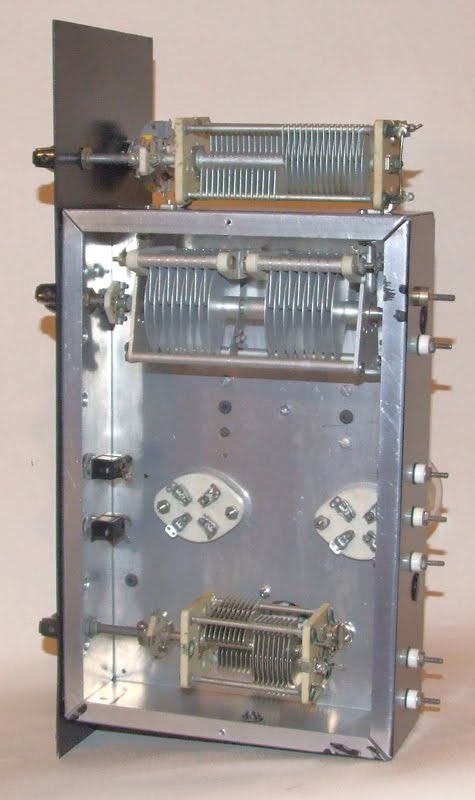
With the chassis and front panel drilled, punched and painted this project should start looking more like a kit. Everything is in hand, all I need to do is mount, wire and solder.
I laid out the chassis and front panel so that eventually this amplifier will serve as an upper deck of a 70 watt CW transmitter. My 1934 transmitter will be the lower deck/driver.
Tuesday, April 13, 2010
Springtime - QRPtime
With an early spring here in SE Minnesota I can start thinking about QRP again. One of my favorite local picnic table QRP spots here in Rochester is Essex Park. It has plenty of space, lots of trees with limbs about right for antenna supports and movable picnic tables. Take a look here for a video on my operating from Essex park. On Saturday I worked N1LU, Don in NH, and K1TG, Roger in CT. K1TG was an especially good QSO. We are both active in the AWA and have worked each other using our vintage stations.
This weekend at Essex Park I also worked on a new antenna. My end fed half wave and full wave wire antennas do a fine job but they require at least one well placed tree. I could use a self supporting antenna. Cabellas (and other big box sporting goods stores) sell a 16.5' collapsible crappie (as in fishing) pole. 16.5' is just about right for half of a 20 meter dipole. On Sunday I setup two of these poles to form a V to support a V (not inverted V) dipole. Read more about this antenna here. It appears to work as well as a straight dipole and it is fairly portable....now I need to find a bare nob of a hill to operate from.
This weekend at Essex Park I also worked on a new antenna. My end fed half wave and full wave wire antennas do a fine job but they require at least one well placed tree. I could use a self supporting antenna. Cabellas (and other big box sporting goods stores) sell a 16.5' collapsible crappie (as in fishing) pole. 16.5' is just about right for half of a 20 meter dipole. On Sunday I setup two of these poles to form a V to support a V (not inverted V) dipole. Read more about this antenna here. It appears to work as well as a straight dipole and it is fairly portable....now I need to find a bare nob of a hill to operate from.
Saturday, March 27, 2010
National TRM 56 MC Transceiver


Last week I acquired a 30's vintage National 56 MC transceiver. Read about this model on my web site at http://www.prismnet.com/~nielw/TRM_TRW/TRMpage.htm . The TRM and the wooden cased TRW were two of the first commercially available VHF radios. At only 6"x6"x7.5" and 8.5 pounds it is amazingly heavy for it's size. The two special National transformers add a lot to the weight.
I don't find much information about the TRM. What I've found is from National's 1935 catalog and a 1933 article that, while it doesn't mention it by name, appears to describe the TRM. None of my catalogs mention the TRM or TRW after 1935 but my TRM has a model tag. National didn't but tags on their equipment until after James Millen left in 1938. This one must be a late model.
Subscribe to:
Posts (Atom)