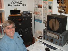
I first started on this project over 15 years ago. I wanted a 6L6 based transmitter with a spotting function. Over the years it has gone through several iterations to the "Dingey Size Boat Anchor" I use today. Along the way I added a loading control, regulated the oscillator plate voltage to 108 volts, shifted the output circuit to a pi network and repackaged it in a metal cabinet to better match my HRO Sr. Like many projects it has been a journey. Here are a few more details about this transmitter as it stands today.
The circuit itself is fairly standard using a separate 300 B+ power supply. About the only thing I don't see in most designs is SW, the spotting switch. It allows me to check my crystal frequency against any station I might want to work or against QRM. As an important serendipity it also allows me to run the oscillator continuously while keying only the 6L6 output stage. This cuts down on chirp caused by the crystal restarting at the beginning of each code element. C10, the loading capacitor, is really two capacitors in parallel. One is a typical 300pf variable. The second is a 300pf high voltage "door knob" capacitor that can be switched it/out with a toggle switch.
Coils are what I could find. The 80 and 40 meter coils are commercial Bud coils that I had. I'm using only the tank portion, not the link. For 30 I found an old plug-in coil that looked about right and tried it. It works. In general look for coils that dip and load to around 60% efficiency (ie. 6 to 7 watts output for 10 to 12 watts input).
Inside I arranged everything so that it made sense. Across the back, left to right, is the 6J5 oscillator, the 6L6 final and then the plug-in output coil. Just to the right of the coil is the toggle switch that switches in/out the additional 300pf loading capacity. The crystal socket is near the 6J5 and the 0C3 108 V voltage regulator is just to the right of that.
When changing crystals or, especially, coils it is important to recognize where high voltage is exposed. In this case the unprotected meter terminals have 300 VDC, a lethal voltage, on them. Power this transmitter down when under the covers. This is even more important when working under the chassis. Don't take chances. Power down before working on it. As a safety modification consider placing the crystal socket on the front panel.
Are you looking for something more modern looking? Try W1TS's 6C4-5763 MOPA in the October 1968 issue QST. Just add a resistor and 0B2 to regulate the oscillator B+ to 108V and include a switch to run the oscillator stage while keying the final.
Showing posts with label 6J5-6L6 Transmitter. Show all posts
Saturday, February 29, 2020
Thursday, February 27, 2020
A Dingey size Boat Anchor on 30 mtrs
After putting my Drake 2B on 30 mtrs I immediately started looking for a matching transmitter. The trouble is, the WARC bands like 30 mtrs weren't created until about 1980, long after the novice requirement for crystal control had gone away. By then solid state VFO controlled transceivers were becoming the typical rig. I'd need to homebrew a transmitter if I wanted vacuum tubes and crystal control on 30 mtrs.
A search of the QST archives brought up three articles that helped me decide what to do. The first was WD8DQT's article in January 2012 showing how to use today's HC49 crystals in simple MOPA (Master Oscillator - Power Amplifier) transmitters. The other two, W1TS's in October 1968 and WD8DAS's in January 2003 each show 6C4 to 5763 MOPA designs that can be modified per WD8DQT's article to use HC49 crystals.
What next?
I already have a crystal controlled MOPA transmitter on my desk. See https://w0vlz.blogspot.com/2008/02/further-6j56l6-transmitter-developments_5846.html . I did a quick check and found that the 6J5 I used is a close match to the 6C4 WD8DQT based his article on. I could start with the 6J5-6L6 transmitter I already had. First I added a VR-105 and 12K 5 watt dropping resistor to power the 6J5 oscillator at 105 VDC. Next I converted the PA to a pi network instead of link coupled output. The tank capacitor is now 140pF and the output/antenna capacitor is now 300pf plus, optionally, an additional 300pF. The coils on 80 and 40 are the same B&W output coils I've been using but without the output link connected. For 30 mtrs I searched through my junque box and found a coil that loads up fine on 30. Finally, I found HC-49 crystals, including 30 mtrs, five for $7.50 on ebay. See https://www.ebay.com/sch/possumlodge/m.html?_nkw=&_armrs=1&_ipg=&_from=
My "new" 6J5-6L6 transmitter uses FT-243 and HC- 49 fundamental frequency crystals. It runs almost 12 watts input and about 6 watts out on 80, 40 and 30 ... outstanding!
See ya on 30.
A search of the QST archives brought up three articles that helped me decide what to do. The first was WD8DQT's article in January 2012 showing how to use today's HC49 crystals in simple MOPA (Master Oscillator - Power Amplifier) transmitters. The other two, W1TS's in October 1968 and WD8DAS's in January 2003 each show 6C4 to 5763 MOPA designs that can be modified per WD8DQT's article to use HC49 crystals.
What next?
I already have a crystal controlled MOPA transmitter on my desk. See https://w0vlz.blogspot.com/2008/02/further-6j56l6-transmitter-developments_5846.html . I did a quick check and found that the 6J5 I used is a close match to the 6C4 WD8DQT based his article on. I could start with the 6J5-6L6 transmitter I already had. First I added a VR-105 and 12K 5 watt dropping resistor to power the 6J5 oscillator at 105 VDC. Next I converted the PA to a pi network instead of link coupled output. The tank capacitor is now 140pF and the output/antenna capacitor is now 300pf plus, optionally, an additional 300pF. The coils on 80 and 40 are the same B&W output coils I've been using but without the output link connected. For 30 mtrs I searched through my junque box and found a coil that loads up fine on 30. Finally, I found HC-49 crystals, including 30 mtrs, five for $7.50 on ebay. See https://www.ebay.com/sch/possumlodge/m.html?_nkw=&_armrs=1&_ipg=&_from=
My "new" 6J5-6L6 transmitter uses FT-243 and HC- 49 fundamental frequency crystals. It runs almost 12 watts input and about 6 watts out on 80, 40 and 30 ... outstanding!
See ya on 30.
Monday, December 10, 2018
Further 6J5/6L6 Transmitter Developments
My shack continues to be in a state of flux, Nothing is built just once. As I rethink things, stuff is added or changed.
In this case I decided to pair my 6J5/6L6 transmitter up with my HRO Sr rather than my Simple Superhet. I wanted something of the right design vintage and looks to sit next to my HRO while running either barefoot or driving my TZ-20 amp. The core design of my 6J5/6L6 transmitter is right out of a 1940 Stancor manual so the design was fine. It just didn't look like it belonged with the HRO Sr. What I did was a cosmetic change replacing the front panel and then repackaging the transmitter in a metal cabinet.
If I ever need a more upscale transmitter in that spot I have a Meissner Signal Shifter waiting in the wings.
In this case I decided to pair my 6J5/6L6 transmitter up with my HRO Sr rather than my Simple Superhet. I wanted something of the right design vintage and looks to sit next to my HRO while running either barefoot or driving my TZ-20 amp. The core design of my 6J5/6L6 transmitter is right out of a 1940 Stancor manual so the design was fine. It just didn't look like it belonged with the HRO Sr. What I did was a cosmetic change replacing the front panel and then repackaging the transmitter in a metal cabinet.
If I ever need a more upscale transmitter in that spot I have a Meissner Signal Shifter waiting in the wings.
Monday, February 25, 2008
Further 6J5/6L6 Transmitter Developments

Using my 6J5/6L6 transmitter in the January AWA OT CW Contest reminded me that my original intent for this transmitter was to have some sort of loading control. In theory L2, the output link, can be wound to properly match a 50 ohm load. In reality I never quite got the power I expected when I used a fixed output link. The solution is to switch to a pi network or add a loading capacitor between L2 and ground.
In keeping with the vintage of the design and the typical output networks of the day I added C10, a loading capacitor, between the output link and ground. C10 is actually a 300pf variable with an old television 300pf doorknob capacitor optionally in parallel with it. The photos show a toggle switch next to the output coil that controls whether the extra 300pf is in the circuit of not. It is needed on 80 but not on 40.
Tuneup is now the standard "dip and load " sort of procedure. Plate current is dipped using C8 and then increased by increasing C10 capacitance. This is repeated until adjusting C10 does not increase plate current. The last step should be to dip the plate current using C8. With a 300 volt (under load) power supply mine easily loads up to about 50mA or 15 watts input.
Subscribe to:
Posts (Atom)