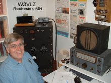
I've had my Push-Pull Colpitts on the air now for about 3 weeks and 10 QSOs. Notable QSOs have included my friend Lou, VE3AWA, in Ontario and W0NYQ, a fellow Minnesotan with a big interest in '29 rigs.
This tranmitter is a keeper. Why?
- Efficiency is 50-60% (great for a '29 power oscillator)
- Drift is measured in the 10s of hertz range. Essentially solid as a rock.
- No hand capacity problem when tuning to get on frequency
- Easy to adjust feedback for minimum plate current and best performance
- "Perfect sounding 1929 signal"
I did receive a report of a trashy buzz on my sidebands. Since then I've been more careful when adjusting the feedback and also the output coupling. I haven't had any other bad reports.
I do still have some trouble with FMing/wobble due to the wind blowing around my antenna. This is a common problem with '29 power oscillators. Whether this is an improvement over my other '29 transmitters, I can't tell.
I haven't cleaned it up on 40 but I can work on that later.
All in all, a really satisfying project.
Tuesday, April 16, 2019

Friday, March 29, 2019
CW on 3565 KHz

Push-pull Colpitts power oscillator on 3565KHz with 6 watts into a low endfed wire as copied by VE7SL in British Columbia, 1490 miles to the west:
Monday, March 25, 2019
It's on the air!
I plan to leave it set up next to my Novice Rig Roundup operating position so that I can put it on the air whenever I want to.

Friday, March 22, 2019
Music to my ears
It works!
Last night I completed the under-the-chassis wiring of my Push Pull Colpitts transmitter. I ended up doing "bus bar" wiring. It gives a 3D effect and worked well for this design/layout. Between that and the wooden chassis this one feels like a '29 transmitter. Most of the under the chassis parts are 40s vintage but, hey, they will be hidden.
 This morning I connected power for an initial checkout. With 300V on the plates and about 20 watts input I'm getting over 10 watts out of sweet sounding RF on 80. The grounded tuning/tank capacitor effectively eliminates the detuning effect of hand capacity and I'm certainly not going to complain about 50% efficiency. Open circuit voltage across the key terminals is only 48 volts so that's good too.
Next I'll clean up the operating position and finish my 40 mtr coils so that I can test it there.

Next I'll clean up the operating position and finish my 40 mtr coils so that I can test it there.
Sunday, February 24, 2019
Push-Pull Colpitts Transmitter - 4

Along the way I've found that Lowes here in Rochester has the best selection of brass nuts, bolts and screws while Albany County Fasteners has the best selection of specialty brass hardware like knurled nuts and wing nuts.
Next I need to plan the layout of the small parts that mount underneath.
Saturday, January 26, 2019
Push-Pull Colpitts Transmitter - 3
 I'm making good progress on my new transmitter. With a lot of help from my friend KE0EXE and his table saw I now have a nice looking oak base. I went ahead and shellacked it so that it looks pretty good. 3/16" copper tubing for the antenna link and 80 meter coil was not available locally so I have to go to Amazon for that but I did find 1/4" tubing for the 40 mtr coil at my local big box hardware store. I added a National type A vernier dial to the Cardwell tuning capacitor. This should help a lot getting on frequency.
The next task is to find all of the screws, nuts and bolts that I need and then start fastening everything in place.
Monday, January 14, 2019
Push-Pull Colpitts Transmitter - 2

The tough part to find was the dual 500 pf Cardwell capacitor. I found one by putting my need out on the AWA Group Yahoo group. What I now have isn't exactly what QST called for but should be close enough. A trip to Menards got me wood for a base. I'll need to pay a visit to a friend with a table saw. Copper tuning I should be able to find locally at Menards, Lowes or Home Depot. The small

Next step is to cut and varnish the base.
Sunday, January 13, 2019
Push-Pull Colpitts Transmitter - 1

I’ve started on a new transmitter for the next AWA Bruce Kelley
1929 QSO Party. The “BK” requires non-crystal-controlled transmitters that are
of 1920s design and use tube types that were available in 1929. I found a
transmitter described in the January 1934 issue of QST that meets these
requirements.

For a good over view of the transmitters built to be used in
the BK take a look at VE7SL’s gallery page at https://qsl.net/ve7sl/29gallery.html
. Of the 65 transmitters 48 are either Hartleys or TNTs. The next one in
the list was the TPTG with 9. Only 2
were Colpitts. I have TNT and Hartley transmitters for the BK and a TPTG is a lot
like a TNT so building a Colpitts for the BK sounds like a good next choice. This
will round out my 1920s “big three”.
The 1934 QST article lists several features of this design
that sound attractive:
Antenna coupling to
the non-plate portion of the tank coil. The more common link coupling to
the plate ends of the tank coil results in more second harmonic output and less
frequency stability when the antenna is tightly coupled for maximum output.
Center/swinging link coupling should be an improvement.
Push-pull tube capacitance
in series. Temperature changes within the tubes that impact the
interelectrode capacities will have less impact on frequency stability. This
configuration also reduces the amount of current through the tubes.
Symmetric layout.
A symmetric layout is less prone to exhibit signal instability
Grounded tuning capacitor
body. In this design the tank tuning capacitor body provides shielding so
that hand capacity has less of an impact on frequency. This transmitter should
be easier to get on frequency.
Easily converted to
an amplifier. If I decide to move on to a MOPA BK rig this will be one
section that I already have.
In addition to information about this particular transmitter
design, this QST article also gives hints that are useful for any 20s
transmitter:
Use a
well-regulated/stiff power supply
Route power and
antenna cables away from the transmitter
Do not place the power
supply close to the transmitter
Now, may the parts hunt begin!
Monday, December 31, 2018
Handbooks on the web
Several ARRL (and Radio) Handbooks can be downloaded from the web ...
1976: https://ia800401.us.archive.org/27/items/RadioAmateurHandbook1976/radio-amateur-handbook-1976.pdf
1941: https://www.scribd.com/document/91745963/The-Radio-Amateur-s-Handbook-1941
1936: http://www.smcelectronics.com/DOWNLOADS/1936%20ARRL%20HANDBOOK.pdf
1931: https://ia802807.us.archive.org/6/items/Amateur_Radio_Handbok_-_ARRL_1931/Amateur_Radio_Handbok_-_ARRL_1931.pdf
Many years of the "Radio Handbook" are at https://www.americanradiohistory.com/Radio_Handbook.htm
For ham radio magazines including QST, CQ and Ham Radio go to americanradiohistory.com . In the upper right corner click on DX logs – SW Ham. From there you will see many many classic radio magazines that you can download.
1976: https://ia800401.us.archive.org/27/items/RadioAmateurHandbook1976/radio-amateur-handbook-1976.pdf
1941: https://www.scribd.com/document/91745963/The-Radio-Amateur-s-Handbook-1941
1936: http://www.smcelectronics.com/DOWNLOADS/1936%20ARRL%20HANDBOOK.pdf
1931: https://ia802807.us.archive.org/6/items/Amateur_Radio_Handbok_-_ARRL_1931/Amateur_Radio_Handbok_-_ARRL_1931.pdf
Many years of the "Radio Handbook" are at https://www.americanradiohistory.com/Radio_Handbook.htm
For ham radio magazines including QST, CQ and Ham Radio go to americanradiohistory.com . In the upper right corner click on DX logs – SW Ham. From there you will see many many classic radio magazines that you can download.
Monday, December 10, 2018
Further 6J5/6L6 Transmitter Developments
My shack continues to be in a state of flux, Nothing is built just once. As I rethink things, stuff is added or changed.
In this case I decided to pair my 6J5/6L6 transmitter up with my HRO Sr rather than my Simple Superhet. I wanted something of the right design vintage and looks to sit next to my HRO while running either barefoot or driving my TZ-20 amp. The core design of my 6J5/6L6 transmitter is right out of a 1940 Stancor manual so the design was fine. It just didn't look like it belonged with the HRO Sr. What I did was a cosmetic change replacing the front panel and then repackaging the transmitter in a metal cabinet.

If I ever need a more upscale transmitter in that spot I have a Meissner Signal Shifter waiting in the wings.
In this case I decided to pair my 6J5/6L6 transmitter up with my HRO Sr rather than my Simple Superhet. I wanted something of the right design vintage and looks to sit next to my HRO while running either barefoot or driving my TZ-20 amp. The core design of my 6J5/6L6 transmitter is right out of a 1940 Stancor manual so the design was fine. It just didn't look like it belonged with the HRO Sr. What I did was a cosmetic change replacing the front panel and then repackaging the transmitter in a metal cabinet.

If I ever need a more upscale transmitter in that spot I have a Meissner Signal Shifter waiting in the wings.
Subscribe to:
Posts (Atom)