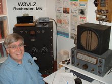
The 2016 Novice Rig Roundup ended last night.
It was neat to hear rigs on the air that I haven't heard in a long time. The NRR also gave me a reason to put my own tube gear on the air. Too often it is easier to sit down, flip on the KX3 and have a QSO. During the NRR, faced with 20 knobs and two meters spread between the 75A4 and Eico 720, I couldn't help but feel master of my universe. There was always one knob more that can be tweaked.
Next year I'll be certain to also have my NC303 / Ranger II combo on the air and, maybe, my Drake B Line.
Saturday, February 27, 2016
Wednesday, February 24, 2016
Novice Rig Roundup
I got my novice ticket in 1966 so this year marks, for me, 50 years of ham radio. Back then I had an Eico 720 and a military surplus BC342. Thursday, February 11, 2016
TNT (and Hartley) Notes
Recently I pulled two early draft papers out of my files that, I believe, were written by W2SN in the early 80s. One was "The Saga of the TNT Transmitter" and the other was "Additional Notes on Self-Excited Oscillators". I posted these at https://www.prismnet.com/~nielw/W2SNPapers/Saga_of_the_TNT_Transmitter.pdf and https://www.prismnet.com/~nielw/W2SNPapers/Additional_Notes_Self_Excited_Oscillators.pdf .
Most of us have had a much better experience with the TNT transmitter than W2SN but I've heard some pretty crummy signals also. There is no doubt that the TNT circuit can misbehave with no one "silver bullet" fix but W2SN tried a lot of fixes and nothing seemed to work. My TNT transmitter certainly sounds better on 80 than on 40. Perhaps most of W2SN's testing was on 40 or, heaven forbid, 20. He also never showed the layout of his transmitter. Perhaps there was a basic problem there.
W2SN does make several points beyond the typical TNT transmitter construction/setup instructions to look at including:
My TNT transmitter shows some (if not all) of the same problems that W2SN saw on 40 mtrs but sounds fine on 80. Next fall I'll look at some of the areas that W2SN mentioned to see if I can get a better signal on 40.
( Have you seen a polished version of these articles? If so, please let me know.)
The 1986 Callbook lists W2SN as Vernon Clifford, Amityville, NY. He got into ham radio in the early 30s using a TNT transmitter. Almost 50 years later he decided to build an exact replica of his first rig. Finished, it looked good but when he put it on the air he got a T7 report with a bad chirp. In these two papers he details what he tried (and learned) as he attempted to clean up his signal.
Most of us have had a much better experience with the TNT transmitter than W2SN but I've heard some pretty crummy signals also. There is no doubt that the TNT circuit can misbehave with no one "silver bullet" fix but W2SN tried a lot of fixes and nothing seemed to work. My TNT transmitter certainly sounds better on 80 than on 40. Perhaps most of W2SN's testing was on 40 or, heaven forbid, 20. He also never showed the layout of his transmitter. Perhaps there was a basic problem there.
W2SN does make several points beyond the typical TNT transmitter construction/setup instructions to look at including:
- Try DC versus AC on the filaments
- If AC filaments, check that the center tap resistor is centered
- Bypass and/or choke the power and keying leads to minimize stray pickup
- Don't use a wood (or wood filler) grid coil form
- Insure a well filtered and stiff B+ supply
- Tune the antenna network to minimize RF in the shack
- Insure a good station ground to minimize RF in the shack
- The value of the grid leak
- The value of the filament bypass capacitors
- Bad feedback stability due to changing tube grid-plate capacitance
My TNT transmitter shows some (if not all) of the same problems that W2SN saw on 40 mtrs but sounds fine on 80. Next fall I'll look at some of the areas that W2SN mentioned to see if I can get a better signal on 40.
( Have you seen a polished version of these articles? If so, please let me know.)
Saturday, February 6, 2016
2016 AWA Linc Cundall Memorial CW Contest (Epilog)
Well, company, schedule conflicts and QRN really cut into my LC
time/score this year. I couldn't get on much and I didn't hear many stations when I did. I ended up working only KA0AAM, W2TAC, AA9DH and KB0ROB.
Still, I did get two of my vintage stations out of mothballs and on the air. That certainly counts for a gold (ok, maybe, bronze) star in my log.
time/score this year. I couldn't get on much and I didn't hear many stations when I did. I ended up working only KA0AAM, W2TAC, AA9DH and KB0ROB.
Still, I did get two of my vintage stations out of mothballs and on the air. That certainly counts for a gold (ok, maybe, bronze) star in my log.
Wednesday, January 6, 2016
2016 AWA Linc Cundall Memorial CW Contest
The "LC" is now only a week away. Over the past few weeks I've been playing with various transmitters and receivers to decide which I'm going to use. Two that I've been working with are a Push-Pull 6L6 transmitter and my version of the 1941 Beginner's Receiver.
This evening I put this pair on 40 mtrs and had a nice QSO with K2UPI in Bridgeport, NY. The signal reports were 569 both ways. This receiver and transmitter worked well together. I'll certainly use them during the LC.
Next I'll make certain my HRO Sr and Utah Jr are working well so that I can use them also, probably on 80.
Addendum, 1/11/2016. This evening I worked Jerry, W1ZB, in Andover, MA on 80 using the HRO Sr and Utah Jr at 15 watts... I'm ready to LC.
This evening I put this pair on 40 mtrs and had a nice QSO with K2UPI in Bridgeport, NY. The signal reports were 569 both ways. This receiver and transmitter worked well together. I'll certainly use them during the LC.
Next I'll make certain my HRO Sr and Utah Jr are working well so that I can use them also, probably on 80.
Addendum, 1/11/2016. This evening I worked Jerry, W1ZB, in Andover, MA on 80 using the HRO Sr and Utah Jr at 15 watts... I'm ready to LC.
Thursday, December 10, 2015
A Winter Vertical
Each winter I shift my primary operating from QRP in the Park to Boat Anchors in the Basement. Two of my favorite winter operating events are the AWA Bruce Kelley 1929 QSO Party and the AWA Linc Cundall Memorial CW Contest. Both of these focus on boat anchors running on 160, 80 and 40 meters. My permanent shack antenna is a trade off at best. I don't have a good way to get much height. For the past several years I've played around with a temporary/winter vertical.
This year I used 7 4' sections of military surplus
fiberglass tubing plus a 5' whip as a 40 meter quarter wave vertical. It is attached to the deck railing at the 9' level and guyed at 24'. I added a loading coil at 13' to get it resonant on 80. This coil is bypassed for 40 meter operation.
After looking at my 80/40 meter vertical I thought, "Hey, I like to operate on 20 also. Let's add a 20 meter quarter wave wire"; good on paper but bad idea. Both the 80/40 meter wire and the 20 meter wire are connected in parallel at the bottom of the vertical. The 20 meter quarter wave wire runs within an inch or two of the 80 meter loading coil. This wire couples into the loading coil changing the resonant frequency by 100-200 KHz...and the resonant frequency varies if the wire flops around in the wind at all. I could watch the
SWR shift as I held the key down. In addition this loading shift really ruins my 29 transmitter tone/signal. Solution: remove the 20 meter element. My winter vertical works fine on 80 and 40 meters, perfect for the AWA operating events.

Some might notice the knotted
rope and pulley attached at the 24' level. For the last two weeks of December and the first days of January my vertical is re-purposed for Christmas decorations. We run a lighted star up it with an attached "tree" of lights.
This year I used 7 4' sections of military surplus
fiberglass tubing plus a 5' whip as a 40 meter quarter wave vertical. It is attached to the deck railing at the 9' level and guyed at 24'. I added a loading coil at 13' to get it resonant on 80. This coil is bypassed for 40 meter operation.After looking at my 80/40 meter vertical I thought, "Hey, I like to operate on 20 also. Let's add a 20 meter quarter wave wire"; good on paper but bad idea. Both the 80/40 meter wire and the 20 meter wire are connected in parallel at the bottom of the vertical. The 20 meter quarter wave wire runs within an inch or two of the 80 meter loading coil. This wire couples into the loading coil changing the resonant frequency by 100-200 KHz...and the resonant frequency varies if the wire flops around in the wind at all. I could watch the
SWR shift as I held the key down. In addition this loading shift really ruins my 29 transmitter tone/signal. Solution: remove the 20 meter element. My winter vertical works fine on 80 and 40 meters, perfect for the AWA operating events.

Some might notice the knotted
rope and pulley attached at the 24' level. For the last two weeks of December and the first days of January my vertical is re-purposed for Christmas decorations. We run a lighted star up it with an attached "tree" of lights.
Wednesday, November 4, 2015
One last visit to the Park
Yesterday it was sunny and the temperature reached 70 degrees, almost 20 degrees above normal for this time of year. Looking at the forecast it looked like this might be one last warm day until next spring. I felt a picnic table calling my name.
Beth picked up lunch at our local KFC while I set up my KX3 and 20 meter zepp at Silver Lake Park here in Rochester. The Reverse Beacon Network showed that conditions were not that good. Only one skimmer gave me a two digit signal report. After going through the effort of setting up I went ahead and called CQ.
The couple of hours on the air/eating lunch/enjoying the weather and company netted me three contacts, about average for me on one of these local QRPxpeditions: WB3AAI/4 / Florida, KF4CLO / Texas and KC2ICA / New York. QSB up and down was the norm for the day. It was neat, though, that KC2ICA was running only 1 watt to a random length wire. That was just 28 miles short of 1000 miles per watt.
Time now to crank up the heat a little and switch over to winter operating ... Boat Anchors in the Basement.
Beth picked up lunch at our local KFC while I set up my KX3 and 20 meter zepp at Silver Lake Park here in Rochester. The Reverse Beacon Network showed that conditions were not that good. Only one skimmer gave me a two digit signal report. After going through the effort of setting up I went ahead and called CQ.
The couple of hours on the air/eating lunch/enjoying the weather and company netted me three contacts, about average for me on one of these local QRPxpeditions: WB3AAI/4 / Florida, KF4CLO / Texas and KC2ICA / New York. QSB up and down was the norm for the day. It was neat, though, that KC2ICA was running only 1 watt to a random length wire. That was just 28 miles short of 1000 miles per watt.
Time now to crank up the heat a little and switch over to winter operating ... Boat Anchors in the Basement.
Monday, September 21, 2015
Travels with a KX3
| Big Bay State Park, Madeline Island, WI |
| Bukolt Park Stevens Point, WI |
My operating style is never highly competitive ... I find a picnic spot with a handy tree (and, maybe, a good view), setup and then call CQ while checking the reverse beacon network to see if anyone might hear me. During this trip I was on both 20 and 30 meter CW working both coasts and as far south as MO. Along the way I also got to talk about ham radio to curious passers-by that happened to notice the wire in the tree and the techie looking gizmo on the table.
Monday, September 7, 2015
1T4 / 3V4 Regenerative Portable - continued
I've tweaked on my 1T4/3V4 regen receiver a little more. (Better headphones for more audio and fixed the bandspread dial slippage/backlash). It is now working pretty good. Here's a little demo video:
Saturday, September 5, 2015
1T4 / 3V4 Regenerative Portable - continued
I've finished my 1T4 / 3V4 Regenerative Portable. Along the way I found Dave's "Regenerative Tube Radio Building Notes" at http://makearadio.com/misc-stuff/regennotes.php . Dave condenses down to a few pages a lot of the information that you need to know about regen receiver design/options without spending a lot of time on theory. It fits his philosophy of "No big theory discussions or math here. You are here to build a radio, not to earn your college degree." This was helpful as I made design changes to fit parts available.
Next, the original design from Bob's Data had both low and high impedance outputs. I'm only using high impedance headphones so I replaced the 10K to 8 ohm output transformer with a 3:1 inter-stage coupling transformer. I had also hoped transformer coupling to my headphones would increase the volume...that didn't happen. More on this later.
I also decided to add an antenna coupling control. I'm not certain this helps a lot but it may come in handy when connected to a long/resonant antenna.
Finally, all of Dave's feedback control options show an RF choke in the B+ line going to the tickler coil. This seemed like a good idea. It keeps the feedback RF all at the coil rather than wandering around the chassis.
Bob's design information included coil winding documentation. I had a set of pre-wound 1930's vintage Hammarlund 6 pin shortwave coils. I used these rather than wind my own coils.
I'm a little disappointed in performance but this is a 1940s/1950s starter set. Maybe this is a good as it gets. Volume is low and the regeneration setting is tricky. When regeneration is set for maximum sensitivity I feel like I'm riding the crest of a wave. Any move may send the set out of CW regeneration or hurt sensitivity. What I'm seeing may be because of the tickler winding. Most references I've found indicate that the correct regen pot setting is at about 12:00. Mine is closer to 9:00...the screen voltage (and, consequently, the 1T4 gain) is pretty low when CW regeneration kicks it. Is this a problem? I don't know. The plate voltage is still the same. I'll have to wind a coil and play with the tickler winding to find out. The other limitation I found was antenna loading impact on the received frequency. Changing my antenna trimmer setting changed the frequency a lot. The solution was to add an RF stage. This won't happen. Once the C1, the bandset capacitor, is set I leave the antenna trimmer alone.
Subscribe to:
Posts (Atom)