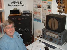
To see if I'm on the air right now click here

Friday, October 30, 2009

More 1928 Hartley

Well, it's in the log...the first QSO. Tonight I worked Lou, VE3AWA, on 3565. We were 549-559 both ways and had a nice contact going until 80 meter QRM caught up with us. Lou was using his Push-Pull TPTG transmitter with a NC101X. I had my HRO Sr paired with the Hartley running 10 watts input and about 3 watts out.

For this contact I added an extension to the main tuning capacitor shaft. Both my TNT and this Hartley are really sensitive to hand capacity. Adding 8" to the tuning shaft helped a lot as I moved onto frequency. I also used a VT-25, the military version of the type 10.

Not obvious in the Hartley list of parts are the National Velvet Vernier dials used by Ross Hull. These make a big difference adding mechanical bandspread to help overcome the 80 meter CW band being crammed into a few degrees of capacitor rotation at one end of its travel.

Lou asked how come my signal was so stable. Antennas swinging in the wind typically shift the transmitter frequency as the load changes. My 105' inverted "L" happens to be a little low (only 10-20' off the ground) and behind a ridge so it is protected from the west winds. I also run with the antenna loosely coupled to the transmitter. Output is only about three watts instead of the 5-6 watts the transmitter is capable of at maximum coupling.

The RF choke is now one I hand wound on a 3/4" piece of wooden rod like Ross Hull's original 1928 design. It doesn't have quite as many turns as he called for but it works fine.

Wednesday, October 21, 2009

More 1928 Hartley


After a little debugging it works!

When I first put power to my version of Ross Hull's Hartley transmitter I could only get it to oscillate if the cathode clip is either not attached at all or clipped to the tank coil near the plate (rather than grid) end. RF with the clip this high on the tank coil is detectable on a nearby receiver but not measurable at the transmitter antenna.

It turned out that all things that look like RF chokes don't make good RF chokes. Mine from my junque box looked like a single layer vintage RF choke, it tested good for continuity and B+ showed up at the tube socket but didn't work well in this circuit. Replacing it with a
more modern RF choke fixed my problem. I'll need to go back and hand wind one like shown in the original 1928 QST article.

I also needed a 4:1 balun to match well to a 50 ohm load.

Now with 300 V B+ and about 25mA input I can push it to over three watts out. Backing off gives me a clean 2 watts out.

Thank you to several AWA friends that helped with parts and advice.


Monday, October 19, 2009

More 1928 Hartley


Except for a couple of coil clips my clone of Ross Hull's 1928 Hartley is complete. It's ready for power and checkout.

Thursday, October 15, 2009

More 1928 Hartley


Today we have surface-mount-technology, before that we had pin-in-hole printed circuit cards, before that point-to-point wiring and before that we had breadboards. With breadboard construction came solid bus bar wiring. Bus bar is stiff enough that wiring takes on a 3D sort of aspect. Wiring of a transmitter such as this Hartley has height along with depth and width.

Wednesday, October 14, 2009

More 1928 Hartley


Working through this project has given me a new appreciation of the homebrewing skills of many of the hams during the twenties and thirties. The article on this particular transmitter has some gaps in the construction details....for coil turn information the builder is referred to the coil photo, to count the turns himself....and....Keying method is a reference to another chapter and, again, left to the builder to figure out.

I chose cathode keying for my version. I also buried the cathode resistors under the tuning capacitor. Keying added two additional Fahnestock clips along the left hand side. From the front mine lays out as keying (hot side), keying (ground side), filament, filament, B-/ground and B+.

Tuesday, October 13, 2009

More 1928 Hartley


That pile of old parts, wood and copper tubing is starting to look like a transmitter. The eight parts left are mostly to be wired into place so things should speed up a little.

The unsung hero of any project like this is a drill press. Without one you could never get all of the holes right.

Friday, October 2, 2009

More 1928 Hartley


With (plexi)glass rods ordered and one additional National DX capacitor in the mail from a friend the next step is some table saw time.

Tuesday, September 29, 2009

A 1928 Hartley

After seeing my 1934 transmitter a friend asked if I was doing anything special for the Bruce Kelley Memorial 1929 QSO Party coming up in December. Last year I put my TNT transmitter and SW3 on the air. This year it might be interesting to try a Hartley oscillator.

As ham radio approached January 1, 1929, and the more rigorous standards, the ARRL encouraged hams to improve their stations. One improved transmitter design was a single tube Hartley oscillator described by Ross Hull in the August 1928 issue of QST. Bruce Howes, W1UJR, covers this design on his web site here.

I've been searching through my junque box looking for the parts I need. The first step was a parts list and an enlarged scan/photo of the transmitter. After picking thr
ough multiple boxes and peanut butter jars I've lots of possibilities. Now it's a matter of sorting through what I have for the parts that match the original design.

Sunday, September 27, 2009

Camping and Picnic Table QRP

This last weekend we planned a campout at Frontenac State Park. We've picniced there several times but have never camped over night. No camping trip packing list is complete without my K1. (This time we did forget the blankets and pillows but the K1 was loaded.)

I ended up getting several chances to ham. After a quick listen on 20 and discovering the CQ WW RTTY contest in full swing I moved to 30 mtrs for the weekend. The antenna was a 45' endfed wire (1/2 length wave on 30 mtrs) in a tree next to the campsite. It was approximately broadside to the NNE but did a great job into the northeast US. Between Saturday and Sunday I worked W3XAF (MD), KB3TJS (MD), W0IMD (CO), AA3TH (PA), WA1IIE (ME) and KD3DK (PA).

Tuesday, September 22, 2009

More 1934 Transmitter

Remember the safety problem with my 1934 transmitter? Two of the phone plugs is for metering and the third is for the key. If, in the heat of the moment, I get the them mixed up and plug the key into a B+ metering jack, I'll have up to 300 volts on the key.

To protect myself I tied a length of string and a plastic cable clamp to the key phone plug (any lump of plastic would work). After the key is plugged in I slide the cable clamp under the front edge of the transmitter. The string is short enough that the plug can not be removed without getting the clamp out from under the transmitter.