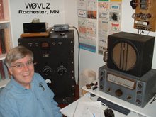
The last two weekends I participated in the AWA 1929 QSO party. The main requirement is that the transmitter be a 1929 or earlier design. I ended up using my two tube TNT (tuned plate - not tuned grid) transmitter (see http://www.io.com/~nielw/tnt/tnt.htm ) while the receiver was a National SW3 three tube regen (see: http://www.io.com/~nielw/nat_list/sw3.htm ). See http://www.io.com/~nielw/1929Stn/1929Station.htm for more information and videos.
I was only on 80 and worked 8 stations, 7 in MN and one, WA3FFC, in PA. MN contacts were W0DGU, K0KCY, W0CWU, WA9WFA, W0NYQ, K0PK AND KB0ROB.
Thursday, December 18, 2008

Sunday, April 27, 2008
A Simplified CW keying monitor
My homebrew CW station shown at http://www.wiegandfamily.org/2tube_xmtr/2tube_xmtr.htm
includes a control (speaker/power supply/TR switch) box. I found, though, that I still needed some sort of CW monitor. The June 1952 issue of CQ magazine describes a simplified CW keying monitor using only 6 parts. Basically it is a neon bulb type audio oscillator keyed by a second neon bulb energized by transmitter RF. I built the circuit into my control box coupling the monitor output to the grid of the 6F6 audio output stage. I added a 12 Meg resistor from B+ to the junction of the two neon bulbs to help reduce motorboating when the circuit is not energized.

It works fine. Now I can silence the receiver on transmit and have the CW monitor to listen to my own fist.


includes a control (speaker/power supply/TR switch) box. I found, though, that I still needed some sort of CW monitor. The June 1952 issue of CQ magazine describes a simplified CW keying monitor using only 6 parts. Basically it is a neon bulb type audio oscillator keyed by a second neon bulb energized by transmitter RF. I built the circuit into my control box coupling the monitor output to the grid of the 6F6 audio output stage. I added a 12 Meg resistor from B+ to the junction of the two neon bulbs to help reduce motorboating when the circuit is not energized.

It works fine. Now I can silence the receiver on transmit and have the CW monitor to listen to my own fist.


Saturday, March 15, 2008
Grinding Crystals
As I played with my 6J5/6L6 transmitter I saw that I had some holes in my 80 mtr crystal selection. I had several crystals at 3550 but practically none between 3550 and 3570. Before stable and well calibrated VFOs were plentiful, grinding crystals was a common activity. Military surplus crystals were obtained cheap and ground to the frequency of interest. I decided to grind some of my 3550 KHz crystals up a few KHz to fill in the gaps in my crystal selection.
I used 400 grit wet sandpaper face up on a flat surface as my grinding "station". I removed the quartz crystal plate from the holder and, pressing on two diagonallyopposite corners, ground in a figure 8 pattern. I'd typically grind for 5 to 10 passes and then rotate 90 degrees, repeating four times. I then cleaned (with rubbing alchohol) and dried the crystal, reassembled it and checked the frequency. If I hadn't shifted it far enough I repeated the whole process. To insure that I ground only one side of the crystal I marked a side with a dot of ink.
I found that my Millen grid dip oscillator and a frequency counter made a handy crystal checker. I plugged the crystal in place of the GDO coil and capacitively coupled one pin to my frequency counter. The counter then read the crystal frequency and the grid current indicated crystal activity.
Additional tips:
- Try to limit the frequency shift. I've never gone beyond about 30 KHz.
- Use a large binder clip to temporarily hold the crystal holder together when you test it. This saves screwing and unscrewing three bolts every time you test for frequency.
I used 400 grit wet sandpaper face up on a flat surface as my grinding "station". I removed the quartz crystal plate from the holder and, pressing on two diagonallyopposite corners, ground in a figure 8 pattern. I'd typically grind for 5 to 10 passes and then rotate 90 degrees, repeating four times. I then cleaned (with rubbing alchohol) and dried the crystal, reassembled it and checked the frequency. If I hadn't shifted it far enough I repeated the whole process. To insure that I ground only one side of the crystal I marked a side with a dot of ink.
I found that my Millen grid dip oscillator and a frequency counter made a handy crystal checker. I plugged the crystal in place of the GDO coil and capacitively coupled one pin to my frequency counter. The counter then read the crystal frequency and the grid current indicated crystal activity.
Additional tips:
- Try to limit the frequency shift. I've never gone beyond about 30 KHz.
- Use a large binder clip to temporarily hold the crystal holder together when you test it. This saves screwing and unscrewing three bolts every time you test for frequency.
Monday, February 25, 2008
Further 6J5/6L6 Transmitter Developments


Using my 6J5/6L6 transmitter in the January AWA OT CW Contest reminded me that my original intent for this transmitter was to have some sort of loading control. In theory L2, the output link, can be wound to properly match a 50 ohm load. In reality I never quite got the power I expected when I used a fixed output link. The solution is to switch to a pi network or add a loading capacitor between L2 and ground.
In keeping with the vintage of the design and the typical output networks of the day I added C10, a loading capacitor, between the output link and ground. C10 is actually a 300pf variable with an old television 300pf doorknob capacitor optionally in parallel with it. The photos show a toggle switch next to the output coil that controls whether the extra 300pf is in the circuit of not. It is needed on 80 but not on 40.
Tuneup is now the standard "dip and load " sort of procedure. Plate current is dipped using C8 and then increased by increasing C10 capacitance. This is repeated until adjusting C10 does not increase plate current. The last step should be to dip the plate current using C8. With a 300 volt (under load) power supply mine easily loads up to about 50mA or 15 watts input.
Tuesday, January 29, 2008
AWA OT CW Contest Operating
Last week was the AWA OT CW Contest. I had hoped to be operating using my 815 transmitter but it continues to run off on it's own as a tuned grid-tuned plate oscillator. I switched to my 6J5/6L6 transmitter ( http://www.io.com/~nielw/2tube_xmtr/2tube_xmtr.htm ) and a NC-101X ( http://www.io.com/~nielw/nat_list/nc100.htm ). The pair worked well together and I had four enjoyable QSOs including WA9QNN, W0LGU, WU2D and AA4RM.
Wednesday, January 16, 2008
More on my 6L6/815 Transmitter

Next Wednesday, January 23, is the AWA Linc Cundall Memorial OT CW Contest. It is about time I get my 6L6/815 Transmitter on the air. Two big stumbling blocks had to be worked on: 1) three different high voltage requirements, 815 B+ around 500 VDC, 815 screen around 250 VDC and oscillator B+ around 150-200 VDC and 2) a tendency of the
 815 to run off on it's own as a tuned grid-tuned plate oscillator.
The original transmitter design called for voltage dropping networks to get the right screen and oscillator voltages. In the end I added a VR tube to even out the voltage to the 6L6. In the 1941 design the 6L6 plate voltage would drop from 500 to 250VDC at key down. The oscillator would over drive the 815 as the voltage dropped, creating harmonics and spurious RF output. It was bad enough that the SWR would bounce up at the beginning of each dit or dah indicating RF temporarily not on the design frequency. The VR 150 at the left rear of the chassis along with a 10K resistor network underneath now keeps the oscillator B+ at 150 VDC, key up and key down. I found the 815 screen voltage to be more forgiving than the 6L6 plate voltage. There I added the recommended power resistor network to drop the screen voltage to an acceptable level. Neither of these solutions are elegant. Between them they waste 25 watts of power but they do work.
The instability of the 815 amplifier is still a problem. A tin can (actually Wolf brand chili can) shield around the 815 grid coil helps a lot, especially if the final is lightly loaded. I still have to tune up carefully, though, or the output looks pretty trashy.
Thursday, December 20, 2007
BA on 20mtrs
Tuesday I got on 14.050 cw using one of my boat anchor stations. The station of choice this time was my Collins 75A3 and Central Electronics 20A. In the mid 50s the 20A was one of the first commercially available SSB exciters but it also works fine on CW running about 20 watts. I use mine crystal controlled. Contacts on Dec 18 in the early afternoon included both W5ZR (LA) and NV4I (SC).
Wednesday, December 19, 2007
AWA 1929 CW Party
With snow on the picnic tables here in Minnesota my operating has moved from K1/QRP to the boat anchors in the basement. The AWA 1929 CW Party occurred the first two weekends of December. This contest requires that the transmitters reflect 1929 or older technology and tubes. Participation is in the 50 - 100 station range so it is a fairly low key "contest". Even the required log information forces operators to slow down as name, QTH, signal report and transmitter descriptions are exchanged. Power is limited to 10 watts input (except for late east-west QSOs) on 80 and 40 meters. Many of the transmitters are self excited Hartley, TNT or TPTG oscillators link coupled to the antenna. Some are MOPA (master oscillator-power amplifier) two stage transmitters. I put my TNT transmitter on the air with my National NC-81X receiver. Running about 2 watts out on 3560 KHz I had seven enjoyable QSOs. Longest "DX" was N4GJV in Cleveland, NC. All of the others were in MN and WI. The contest was not without some last minute challenges, but not with the 1929 gear. As I got started I realized that I had no way to zero beat my signal. The '81X muting function has no mute bypass switch. With it wired into my T-R relay to mute on transmit I had no way to tune my receiver to listen for my own frequency. Fortunately the '81X is ham band only with relatively good calibration so I wasn't to far off ... but then the NC-81X receiver dial string broke. My receiver could be tuned just fine but I had no direct frequency readout. I made it through the contest by listening for a signal of known frequency and then not straying far from that. It was a fun evening.
Monday, November 26, 2007
More NC-57
I added a Heathkit QF-1 Q-Multiplier ( http://www.heathkit-museum.com/ham/hvmqf-1.shtml ) to my NC-57. The QF-1 provides additional selectivity or signal rejection as desired. It was marketed by Heathkit starting around 1956 and was a fairly common accessory. It requires a connection to the IF stage plus B+ and filament voltages available at the NC-57 accessory socket.
I found this to be a big help. The QF-1 effectively eliminated the CW audio image (ie. a readable signal each side of zero beat) common in receivers that don't have a crystal filter. Eliminatling the audio image eliminated half the QRM on the band.
I found this to be a big help. The QF-1 effectively eliminated the CW audio image (ie. a readable signal each side of zero beat) common in receivers that don't have a crystal filter. Eliminatling the audio image eliminated half the QRM on the band.
Wednesday, November 21, 2007
NC-57 Project with comments about the NC-125

My set had been already gone through by a previous owner, recapped and aligned. This set includes an extra dial string in the bandspread tuning assembly to overcome slipping. While this radio generally worked it also would go dead once and a while for no apparent reason. Close inspection revealed a cracked solder connection on a filament pin of the 6H6 detector. Resoldering this connection fixed the problem.
Properly aligned, the calibration was excellent and sensitivity good but this radio is still only one step removed from a simple SWL receiver. Mechanical and electrical stability is marginal, especially above 40 mtrs. It was no surprise that SSB and CW signals easily overloaded the receiver and BFO. Operation with the BFO requires running the AF gain wide open and controlling volume with the RF gain control. I did like the positive feel of the main tuning. While National used a failure prone dial string for bandspread tuning, main tuning uses a gear/pinch wheel mechanism.
Three years after introducing the NC-57 National came out with the NC-125. Under the covers this "new" receiver was simply a NC-57 with the internal speaker replaced by an S-meter and Select-O-Ject audio filter. Both of these features were available as options on the NC-57. National also replaced the round dials with slide rule dials. Unfortunately National took a step backwards by using slip prone dial strings on both the bandspread and main tuning. The Select-O-Ject feature, while unique, does nothing to remove the audio image. I believe a Q-multiplier similar to the Heathkit QF-1 would have been more useful.
I acquired a tilt base with my NC-57. Besides tilting the radio front for easier reading, this also allows a ham to add extra station controls and some accessories without cluttering up the shack. High on my list is a 1MHz crystal calibrator to help set the main tuning for repeatable bandspread calibration over each ham band.
I plan to use my NC-57 on 80 and 40 with one of my early novice transmitters.
Subscribe to:
Posts (Atom)