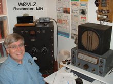
This last weekend we planned a campout at Frontenac State Park. We've picniced there several times but have never camped over night. No camping trip packing list is complete without my K1. (This time we did forget the blankets and pillows but the K1 was loaded.)
I ended up getting several chances to ham. After a quick listen on 20 and discovering the CQ WW RTTY contest in full swing I moved to 30 mtrs for the weekend. The antenna was a 45' endfed wire (1/2 length wave on 30 mtrs) in a tree next to the campsite. It was approximately broadside to the NNE but did a great job into the northeast US. Between Saturday and Sunday I worked W3XAF (MD), KB3TJS (MD), W0IMD (CO), AA3TH (PA), WA1IIE (ME) and KD3DK (PA).
Sunday, September 27, 2009

Tuesday, September 22, 2009
More 1934 Transmitter
Remember the safety problem with my 1934 transmitter? Two of the phone plugs is for metering and the third is for the key. If, in the heat of the moment, I get the them mixed up and plug the key into a B+ metering jack, I'll have up to 300 volts on the key.
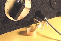
To protect myself I tied a length of string and a plastic cable clamp to the key phone plug (any lump of plastic would work). After the key is plugged in I slide the cable clamp u nder the front edge of the transmitter. The string is short enough that the plug can not be removed without getting the clamp out from under the transmitter.

To protect myself I tied a length of string and a plastic cable clamp to the key phone plug (any lump of plastic would work). After the key is plugged in I slide the cable clamp u
 nder the front edge of the transmitter. The string is short enough that the plug can not be removed without getting the clamp out from under the transmitter.
Wednesday, September 16, 2009
A 1934 transmitter - On the Air
Yesterday I set up my 1934 transmitter up with my NC101X and tried the pair out on 80 meters using my endfed 105' inverted  "L" antenna only about 10'-20' off the ground. The station worked fine.
At 21:45 I had a nice QSO on 3570 with NG9D in Plainfield, IL. Lynn's signal varied from 589 to 599+. He reported that my 589 signal sounded fine/stable.
Also shown in the picture is my iambic keyer set up to key older tube rigs.
 "L" antenna only about 10'-20' off the ground. The station worked fine.
At 21:45 I had a nice QSO on 3570 with NG9D in Plainfield, IL. Lynn's signal varied from 589 to 599+. He reported that my 589 signal sounded fine/stable.
Also shown in the picture is my iambic keyer set up to key older tube rigs.
Sunday, September 13, 2009
More 1934 transmitter - It Works!
I've finished wiring my 1934 transmitter, powered it up and it works! With about 300 volts
  on the plates of the 46s
  and the 47 it loads to 15-20 watts input and 7-10 watts output. It sounds great also.
One change I made from the Bill Orr design is to connect the 47 screen to regulated 150V rather than a resistor network off of B+.
This transmitter is not without some personality, though. Only the amplifier stage is keyed so the oscillator stage runs continuously. On key up any energy from the oscillator that makes it to the antenna will be heard as a faint back wave. We'll see if this is objectionable. The second personality trait is, unfortunately, pretty nasty. When using the rig, two phone jacks are for metering plate current and the third is for the key. If in the heat of the moment I get the three mixed up and plug the key into a metering jack I'll have over 300 volts on my key. To make matters even worse, keying the metering/B+ line works so I may not even be aware of what I've done until I get myself between the key and ground. I'm planning something that will keep me from accidentally removing the key plug.
Eventually I plan is to mate this transmitter with my National FB7X for a complete 1934 station that I'll use in the 2010 AWA Linc Cundall OT CW Contest.
 transmitter, powered it up and it works! With about 300 volts
  on the plates of the 46s
  and the 47 it loads to 15-20 watts input and 7-10 watts output. It sounds great also.
One change I made from the Bill Orr design is to connect the 47 screen to regulated 150V rather than a resistor network off of B+.
This transmitter is not without some personality, though. Only the amplifier stage is keyed so the oscillator stage runs continuously. On key up any energy from the oscillator that makes it to the antenna will be heard as a faint back wave. We'll see if this is objectionable. The second personality trait is, unfortunately, pretty nasty. When using the rig, two phone jacks are for metering plate current and the third is for the key. If in the heat of the moment I get the three mixed up and plug the key into a metering jack I'll have over 300 volts on my key. To make matters even worse, keying the metering/B+ line works so I may not even be aware of what I've done until I get myself between the key and ground. I'm planning something that will keep me from accidentally removing the key plug.
Eventually I plan is to mate this transmitter with my National FB7X for a complete 1934 station that I'll use in the 2010 AWA Linc Cundall OT CW Contest.
Friday, August 28, 2009
QRP Operating at Crater Lake National Park

After three weeks, 5300 miles and 12 western states Beth and I are back in Rochester. I took along my K1 in a lunch bag so that I'd be ready for any ham opportunities.
One of our tourist stops was Crater Lake in southeastern Oregon. On August 19 I found a tree stump overlooking the lake, threw a 32' length of wire into a nearby tree and got on 20 meters. My location was on the western rim of the 5 mile wide caldera with the water around 800' below me. After a few CQs I worked Jim, W0CML, near Denver. Once he swung his beam around he was nice copy at 589 and I was 579. After supper that evening I operated on 40 from in front of our cabin at Mazama Village, 7 miles and about 1000' below the rim. Tim, AD7AN, in San Diego gave me a 529 while he was 579 for me.
"Picnic table QRP" continues to be a fun way to spend some spare time while traveling.
Thursday, July 9, 2009
More 1934 Transmitter

I've gotten the components all mounted and the transmitter is ready for wiring. I learned a few things along the way...
30s vintage Sangamo mica capacitors are large enough that they don't mount well on their own leads. Each one must be mechanically supported, either by a solder strip or by screwing to the wooden sides of the chassis.
The wooden chassis takes 1 1/2 inches of available length and width. This can impact the layout. Using an all metal chassis there is space for a buffer stage between the oscillator and amplifier. With 1 1/2 taken off the length/width plus the added reinforcing across the middle it would be a challenge to fit the buffer stage in there.
Will the lead length be a problem? Certainly I wouldn't trust this spread out layout at 30MHz but it may be OK on 7MHz. Time will tell.
Monday, July 6, 2009
QRP from Frontenac State Park
Sunday afternoon, July 5, I got  over to Frontenac State Park for some picnic table QRP. The picnic area there sits at the edge of a 400' bluff over looking the Mississippi River. Below the park is Lake Pepin , a naturally wide part of the upper Mississippi. To the east, across the Mississippi/Lake Pepin, is Wisconsin. The weather Sunday was sunny but not too warm in the shade, perfect for picnic table QRP.
Using my K1 running 4 watts and feeding a 67' end fed wire I worked K4BAI(Columbus, GA), WA3PAK(Marion, OH) and N7JOX(northern CO near Cheyenne, WY). All in all a satisfying and relaxing afternoon....
 over to Frontenac State Park for some picnic table QRP. The picnic area there sits at the edge of a 400' bluff over looking the Mississippi River. Below the park is Lake Pepin , a naturally wide part of the upper Mississippi. To the east, across the Mississippi/Lake Pepin, is Wisconsin. The weather Sunday was sunny but not too warm in the shade, perfect for picnic table QRP.
Using my K1 running 4 watts and feeding a 67' end fed wire I worked K4BAI(Columbus, GA), WA3PAK(Marion, OH) and N7JOX(northern CO near Cheyenne, WY). All in all a satisfying and relaxing afternoon....
Sunday, May 31, 2009
More 1934 Transmitter
After some quality table saw time, a bunch of drill press time and eight coats of paint (primer coat, satin black, three coats of wrinkle paint that didn't wrinkle and three more coats that did) I have a wood and aluminum chassis that looks pretty good. The layout is much like the Gross CW-25 but without the buffer stage. In place of the middle/buffer tuning dial I'm mounting a plate current meter. Across the bottom are three 1/4" phone jacks. One is the key jack. The other two are in the B+ circuits of the oscillator and final amp stages. These two jacks will have 350VDC exposed on the outside rim. For safety I recessed these jacks 1/2" behind the front panel. I also added a B+ switch on the far right.
I found two more examples of this tube lineup. One is a George Grammer construction project covered in November 1932 and February 1933 QST. The second is the Collins 4A transmitter.


I found two more examples of this tube lineup. One is a George Grammer construction project covered in November 1932 and February 1933 QST. The second is the Collins 4A transmitter.


Friday, April 10, 2009
More 1934 Transmitter

After collecting all of the parts comes "playing checkers" to find the best layout given the set of parts located. In this case I found suitable 30's parts for all of the major components except the chassis itself. For it I'm using a 17"x10" sheet of 18 gauge aluminum. It will be fastened to a 4 1/2" tall wooden frame and then frame and aluminum painted black winkle.
Thursday, April 9, 2009
A 1934 Style Transmitter
Since the AWA Linc Cundall OT CW Contest in January I've been thinking about building another transmitter, this one falling in between my 1929 TNT transmitter and my Thordarson 100 or late 30's 6L6 transmitters. I want to use it with my National FB-7 so it needs to be an early to mid 30's design.

A popular design in the early 30's used a type 47 as a crystal oscillator driving a buffer and final on 160 through 10 meters. Typical power was anywhere from 20 watts on up depending on the tube lineup. The Gross CW-25 was one example. It had a 47 oscillator driving a 46 buffer/multiplier followed by two 46s in parallel. Plug-in coils were available for all bands 160 - 10. This looks like a pretty neat transmitter. More about the CW-25 can be found in Bill Orr's "Antennas" column in the February 1977 issue of CQ magazine.
I wish I could find a CW-25 available. Does anyone have one they will part with? In the mean time I'll have to homebrew something.

The cover story of the November 1971 issue on CQ magazine is a Bill Orr construction article describing a 160/80/40 meter "1934 Style Transmitter". Circuit-wise it is a close match to the CW-25 but without the buffer/multiplier stage. This circuit design fits my early/mid 30's requirement but the CW-25 chassis sort of construction better matches the "modern" look of my FB-7. I'll combine the two using the circuit from Bill Orr's article but building it to look more like the CW-25.
Notice that the schematic scanned from the original CQ article is missing the connection between the coupling capacitor C6 and the 46 tube grids.

A popular design in the early 30's used a type 47 as a crystal oscillator driving a buffer and final on 160 through 10 meters. Typical power was anywhere from 20 watts on up depending on the tube lineup. The Gross CW-25 was one example. It had a 47 oscillator driving a 46 buffer/multiplier followed by two 46s in parallel. Plug-in coils were available for all bands 160 - 10. This looks like a pretty neat transmitter. More about the CW-25 can be found in Bill Orr's "Antennas" column in the February 1977 issue of CQ magazine.
I wish I could find a CW-25 available. Does anyone have one they will part with? In the mean time I'll have to homebrew something.

The cover story of the November 1971 issue on CQ magazine is a Bill Orr construction article describing a 160/80/40 meter "1934 Style Transmitter". Circuit-wise it is a close match to the CW-25 but without the buffer/multiplier stage. This circuit design fits my early/mid 30's requirement but the CW-25 chassis sort of construction better matches the "modern" look of my FB-7. I'll combine the two using the circuit from Bill Orr's article but building it to look more like the CW-25.
Notice that the schematic scanned from the original CQ article is missing the connection between the coupling capacitor C6 and the 46 tube grids.

Subscribe to:
Posts (Atom)