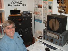
After a couple of days scratching my head and asking around trying to figure out why my TZ-20 amplifier wasn't working up to expectations I finally did what I should have done first. I

checked the wiring.
One TZ-20 wasn't connected to the final tank coil. I was running with only half an amplifier and a poorly designed one at that. It worked but not well. Once I fixed the wiring error power levels jumped to the 50-60 watt range. Neat, but now I needed to deal with typical amplifier problems.
TPTG feedback -The first problem I had was that the amplifier took off on it's own (without any drive) when the input/grid circuit was peaked for maximum output. This was solved by removing C3, the TZ-20 grid tuning capacitor, from the circuit. C3 in the amplifier and C8 in the final tank circuit of my 1934 transmitter interacted anyway so this eliminated one pesky control. Problem solved but now the drive level was

way down...one solution led to another problem.
Drive level - With no tuned circuit on the grids of my TZ-20s they were not getting the drive needed to get anywhere close to full output. This one was solved with a new coil for L1/L2. More turns for L2 got the power transfer up to the point that now I'm easily driving the amplifier to 75 watts input.
Bias - This all started with me wondering if I has the bias set right. The advantage of the TZ-20s is that they do not need an external bias supply to protect them when the drive goes away. With no drive (and no bias) plate current drops to almost zero. For the TZ-20 a simple resistor from the grid to ground is all that's needed to produce needed bias....but what value? It turns out that the 1939 Taylor tube manual has a formula for calculating recommended Class C CW grid bias for a given plate voltage, in my case 500V. Bias came out approximately 20 volts. I'm driving the grids to about 30mA ... 20V/30mA = 666 ohms. I had a 750 ohm resistor, close enough.
One question that had to be dealt with was how best to couple the output to the antenna. It turns out that, for my 40 turn tank coil, a four turn link gives me maximum output into my 50 ohm dummy load. I am set up, though, so that I can add a loading capacitor in series with the link to cover real world antenna conditions.
Now I have an amplifier for
my 1934 transmitter that takes about 6 watts of drive to run 75 watts input (45-50 watts output) on 80. With a couple of new coils I should be able to put it on 40.
Look for me during the
AWA Linc Cundall OT CW contest next week.
 Obviously I'm not a major contester. During the 48 hour contest I netted nine contacts. Not many contacts/points but I did enjoy putting my latest homebrew transmitter on the air.
 1934 style oscillator-buffer deck driving two Taylor TZ-20s in push-pull. The receiver was a National NC-101X. Everyone that commented indicated that the transmitter sounded fine. Keying the buffer stage helped. With the crystal oscillator running continuously (on transmit) there was no sign of chirp.


